BIM Designer — GUI Architecture from Existing Infrastructure¶
Foundation: BBC · DATA_MODEL · BIM_COBOL · MANIFESTO · TestArchitecture
Version: 1.1 (2026-03-17) Depends on: BOMBasedCompilation.md, MANIFESTO.md, BIM_COBOL.md
The compiler already knows how to build. The GUI is a parameter chooser that triggers compilation and shows the result. Every concept the designer needs already exists in the codebase — tack convention, BOM selection cascade, M_BOM_Line spatial relationships (dx/dy/dz), BIM COBOL verbs, EntityType governance.
Phase G Preamble — Proven Artifacts the Designer Builds On¶
The BIM Designer (Phase G) does not start from scratch. Three Rosetta Stone buildings — SH, DX, TE — have proven the full pipeline end-to-end: IFC extraction → component library → BOM dictionary → 12-stage compilation → verified output. All gates GREEN (G1–G6).
The designer works on these already-proven artifacts:
| Artifact | What it is | Where | Designer touches it |
|---|---|---|---|
classify_*.yaml |
Building identity + Order input (onboarding only) | IFCtoBOM/src/main/resources/ |
Legacy IFC onboarding; generative buildings use Work Orders |
{PREFIX}_BOM.db |
Spatial arrangement — m_bom + m_bom_line | library/ |
Sets attributes, quantities, tack offsets |
component_library.db |
Product catalog + geometry meshes | library/ |
Snaps correct geometry to products |
dsl_*.bim |
Building definition language | IFCtoBOM/src/main/resources/ |
Grid, rooms, openings, construction system |
*.bimcobol |
Verb scripts | DAGCompiler/lib/input/ |
Post-compile actions (route, wire, place) |
Output .db |
Compiled spatial DB | DAGCompiler/lib/output/ |
Read-only — Bonsai renders this |
The two-DB split is critical: The designer edits the BOM (spatial arrangement) and the library (product catalog) — never the output. The output is always a fresh compilation from those sources. This is the same separation as ERP: you edit the Bill of Materials and the Product Master, not the finished goods inventory.
BOM vs output — the instancing boundary: The BOM is a recipe, not an inventory. It should contain unique product models with quantities and pattern rules — the compiler then expands those into placed instances in the output DB. The correct split:
BOM (recipe):     505 products × pattern formulas  →  ~200 lines
                  "20 plates at 600mm spacing along roof grid"

Output (result):  48,428 placed element instances
                  each with world-coordinate position + library geometry
The current TE BOM has 48,428 unfactored placement rows — one per element with its own dx/dy/dz. This proved the pipeline round-trip (7/7 GREEN) but conflates BOM recipe with compiled output. A proper factored BOM compresses repeating patterns into formulas with quantities; the compiler expands them to output instances. This factorization (TE-6 TILE SURFACE compression: 34K ARC plates → ~20 formulas) is a prerequisite for the designer — you edit pattern rules, not 48K individual placements. See BBC.md §1 for the BOM dimension model.
Federation Menu — Item 0: Compile / Item 1: Preview / Item 2: Create New¶
The Bonsai addon's Federation menu has three entry points:
| Item | Action | Data source | Use case |
|---|---|---|---|
| 0. Compile | Runs 12-stage pipeline → fresh output.db | YAML + BOM DB + component library | Design iteration: edit → compile → view |
| 1. Preview / Full Load | Loads extracted reference DB directly | *_extracted.db (raw IFC data) |
Inspection: view the reference as-is |
| 2. Create New | Spawns settings dialog → generates BOM → compiles | User choices + component library | Generative: design a new building from scratch |
Item 0 is the designer path — it produces output.db from source artifacts. Item 1 is the review path — it loads existing IFC extraction for comparison. Item 2 is the generative path — it creates source artifacts from user intent. The three never mix data sources.
Item 2: Create New — The Generative Entry Point¶
"Create New" spawns a settings dialog that collects the minimum inputs needed to generate a building from scratch. No IFC file, no extraction — pure intent.
Dialog fields (iDempiere DocType + C_Order pattern):
| Field | Source | iDempiere analogy |
|---|---|---|
| Building name | User input | C_Order.DocumentNo |
| Building type | Dropdown from M_Product_Category (building products) | M_Product selector |
| Jurisdiction | Dropdown: MY, US, UK, AU, SG | C_Order.C_Country_ID |
| Rooms | Checklist: LIVING, KITCHEN, BEDROOM×n, BATHROOM×n | C_OrderLine product selection |
| Site dimensions | Width × depth (mm) | AABB envelope |
| Storeys | Count: 1, 2, 3 | BOM tree depth |
What happens on "Create":
1. Generate C_Order + C_OrderLine (Work Order = building spec)
2. Generate C_DocType entry (Provenance='GENERATIVE')
3. Generate m_bom hierarchy (BUILDING → FLOOR → ROOM) — storeys auto-discovered
4. DocValidate fires: check each room against AD_Val_Rule for jurisdiction
   → BLOCK if bedroom < 3000mm (UBBL), < 2134mm (IRC), etc.
5. CompilationPipeline.run() → output.db
6. Bonsai reloads viewport → user sees their building
Building codes drive the choosers. The jurisdiction selection activates the matching AD_Val_Rule set (DocValidate.md §11). This constrains slider ranges (bedroom min = code minimum, max = site envelope), filters product compatibility (door min width = 750mm MY / 813mm US), and sets ceiling heights. The codes are not a post-hoc check — they are the component chooser data.
| Jurisdiction | Bedroom min dim | Ceiling height | Door min width |
|---|---|---|---|
| MY (UBBL) | 3000mm | 2600mm | 750mm |
| US (IRC) | 2134mm (7 ft) | 2134mm (7 ft) | 813mm (32") |
| UK (NDSS) | 2150mm | 2300mm | 750mm |
| AU (NCC) | — | 2400mm | 820mm |
| SG (BCA) | — | 2400mm | 850mm |
WYSIWYG Editing — Move in Output Space, Write to Source Artifacts¶
The user's experience is WYSIWYG: they move elements in the 3D viewport (output.db space) and see the result immediately. But the actual writes go to the source artifacts, not to output.db — because output.db is always recompiled from sources.
User drags element in Bonsai viewport (output.db coordinates)
  │
  ├─ Addon detects: which BOM line? which product? which storey?
  │  (reverse lookup: output GUID → element_ref → m_bom_line.bom_child_id)
  │
  ├─ Writes to source artifact:
  │  ├─ Order change?     → C_OrderLine (discipline, room selection)
  │  ├─ BOM change?       → m_bom_line dx/dy/dz in {PREFIX}_BOM.db
  │  ├─ Attribute change?  → M_AttributeSetInstance (per-instance params)
  │  └─ Rule override?    → C_OrderLine ASI (guarded by Val_Rule)
  │
  ├─ Recompile (12-stage pipeline)
  │
  └─ Bonsai reloads output.db → viewport updates
Guard rails: Every write to a source artifact is validated by the same rules that guard compilation: - Val_Rule on C_OrderLine — fire protection spacing, structural clearance - EntityType guard — D (dictionary) vs U (user) vs A (application) - BomValidator QA — runs before BOM commit, rejects broken data
The user moves freely in output space. The system translates their intent into source artifact writes. If a move violates a rule, the compiler flags it at recompile — the user sees the violation in the viewport, not in a log.
1. Architecture: Compiler-Driven Editing¶
The GUI does not create geometry. The compiler does. The GUI edits BOM parameters and triggers batch compilation — the same way iDempiere processes a document: Draft → Process → Complete.
┌─ Bonsai (Blender) ─────────────────────────────────┐
│                                                      │
│  Viewport ←── reads ←── FederatedModel spatial DB ─┐ │
│     ↑                         ↑                    │ │
│  refresh                   writes                  │ │
│     │                         │                    │ │
│  Addon Panel ──→ subprocess ──→ Java Compiler      │ │
│  (Python)                       (12-stage pipeline) │ │
│                                                    │ │
│  choosers/sliders → BIM COBOL verbs → compile → DB │ │
│                                                    │ │
│  witness.json ← read ← compliance status display   │ │
└────────────────────────────────────────────────────┘
Data flow: No file handoff during editing. The compiler writes to the spatial DB. Bonsai reads it. IFC export is a final step for permit submission.
Batch model: The user edits parameters, clicks "Process" (iDempiere DocAction pattern). The 12-stage pipeline runs end-to-end. Results appear in the viewport. No keystroke-triggered recompile.
What Bonsai provides free: LOD400 3D rendering, section cuts, element selection, property inspection, dimensioning, Blender's addon panel framework. The only addition is a thin Python addon with chooser panels and subprocess compiler invocation.
2. Existing Concepts That Enable the Designer¶
Every concept below is already implemented and tested. The GUI wires them together — it does not invent new abstractions.
2.1 Tack Convention → Drag-and-Drop Placement¶
The tack convention (BOMBasedCompilation.md §4) makes placement purely algebraic:
- Left-Back-Down corner = (0,0,0) in every BOM's coordinate frame
- dx/dy/dz always >= 0 (enforced at schema level by
X_M_BOMLine.setDx()) - tack_to/tack_from = Lego-style connection points
- rotation_rule on m_bom_line handles orientation
GUI actions map directly to BOM operations:
| GUI action | BOM operation |
|---|---|
| Drag BOM into room | ADD LINE — dx/dy/dz = drop position |
| Slide along wall | Update dx or dy (constrained axis) |
| Rotate 90° | Update rotation_rule |
| Fill gaps | Insert BUFFER PHANTOM lines |
| "Save as BOM" | CREATE BOM + ADD LINE per child |
The tack handshake is uniform at every level: building on site, storey in building, room in storey, furniture in room. Same snap/slide/rotate interaction at every zoom level.
2.2 BIM COBOL Verbs → Editor Action Vocabulary¶
The GUI emits BIM COBOL verbs (BIM_COBOL.md), never direct SQL. 38 verbs in 5 tiers provide the editor's action vocabulary. The GUI is the editor. BIM COBOL is the source code. The compiler is the build system. The user never sees BIM COBOL directly — just as most programmers never see assembler.
Verb-to-GUI action mapping (BIM_COBOL.md §18.12):
| User Action in Bonsai | Verb Emitted | Level |
|---|---|---|
| Draw building envelope | EXTRACT AABB + SNAP TO GRID |
Util |
| "New Building" wizard | COMPOSE BUILDING |
3 |
| Drag room into floor | ADD ROOM |
2 |
| Resize room handle | RESIZE ROOM |
1 |
| Drop furniture into room | FURNISH ROOM |
1 |
| Remove room | REMOVE ROOM |
2 |
| Mirror/rotate unit toggle | SET ROTATION (primitive) |
0 |
| Move element | SET TACK (primitive) |
0 |
| Create empty room | CREATE ROOM ... EMPTY |
1 |
| Clear room contents | STRIP ROOM |
1 |
| Check room fits | VALIDATE AABB |
Util |
| Preview floor layout | PARTITION AABB |
Util |
| Create variant | VARY BUILDING |
5 |
| Clone a design | CLONE BOM |
Data |
Layered composition: L1 convenience verbs call P0 primitives. L2 (floor-level) will call L1. The GUI always targets the highest available verb tier. Each verb produces an audit trail via W_Verb_Node.
Verb chaining (BIM_COBOL.md §18.11) — the output payload of one verb feeds as input to the next. This is how the GUI builds a building interactively:
Step 1: User draws a box in Bonsai
  EXTRACT AABB FROM POINTS (0,0,0) (12.0,10.0,6.0)
    → AabbPayload: WIDTH 12000 DEPTH 10000 HEIGHT 6000

Step 2: Snap to structural grid
  SNAP TO GRID AABB 12000 10000 SPACING 1000
    → GridSnapPayload: WIDTH 12000 DEPTH 10000

Step 3: Preview the spatial partition
  PARTITION AABB 12000 10000 3000 INTO ROOMS LI DN KT BD BT
    → PartitionPayload: 5 slots with positions
    -- GUI shows the partition overlay on the drawn box
    -- User approves or adjusts room positions

Step 4: Compose the building
  COMPOSE BUILDING RESIDENTIAL 12000 10000 6000 UNITS 2
    → ComposeBuildingPayload: 12 BOMs, 47 lines

Step 5: User clicks on kitchen, drags to resize
  RESIZE ROOM KITCHEN_3500x2500 TO 4000 3000 2800
    → ResizePayload: 2 cabinets added, 0 dropped

Step 6: Compile and preview
  PLACE BOM → output.db → Bonsai viewport
Each step is an atomic verb with a typed payload. The GUI can checkpoint
after any step, undo by reversing the {PREFIX}_BOM.db writes, and resume from any
point.
Round-trip editing: If the user moves an element manually in Bonsai (drag in 3D viewport), the system detects the change and updates the BIM COBOL representation via override annotations:
ROUTE SPRINKLERS IN "departure" SPACING 3000mm BELOW_CEILING 150mm {
    OVERRIDE SPR_017 AT (45200, 23100)  -- user manually repositioned
    OVERRIDE SPR_023 OMIT              -- user deleted (column obstruction)
}
Overrides are first-class syntax. The compiler honours them, re-routes around them, and re-proves compliance including the overrides. If an override violates a code rule, the compiler flags it.
BOM namespace discipline (BIM_COBOL.md §18.13):
| Prefix | Source | GUI access |
|---|---|---|
| BUILDING_* | Root BOMs (no parent m_bom_line) | Read-only reference |
| SY_* | Synthetic (created by verbs) | Fully mutable |
The GUI creates and modifies SY_ BOMs only. EntityType='D' guards protect dictionary records at the PO layer. (Historical: EB_/WT_ prefixes removed 2026-03-10, replaced by BUILDING__STD naming.)
2.3 Spatial Relationships → Visual Slots¶
Spatial relationships live in M_BOM_Line dx/dy/dz — the BOM itself carries WHERE information (MANIFESTO.md §Three Concerns). Visual slots in the GUI are derived from BOM spatial data:
- Each M_BOM_Line's dx/dy/dz defines the tack offset (where child sits in parent)
- Structural tiers (unit, slab, floor, room) are BOM levels with spatial offsets
- Empty filler space = PHANTOM BOM line, queryable via SQL
- The GUI presents these as visual room/wall slots for drag-and-drop placement
Implementation note: co_empty_space tables were removed S74 (W008). The source of truth for placement is M_BOM_Line dx/dy/dz directly.
2.4 Selection Cascade → Auto-Fit¶
When the user places a room or furniture set, the BOM selection cascade (BOMBasedCompilation.md §3) finds the best match:
- BomCategory (scope) — restricts to correct functional type
- AABB fit (primary) — product must fit in the available space
- Largest volume (secondary) — maximize space usage
- seq_no (tiebreaker) — lower preferred
The user can BOM Drop to navigate the tree and swap/add products (same bom_category constraint). Without BOM Drop, compile explodes the tree automatically (Instant Drop). See BBC.md §3.3-3.4.
2.5 EntityType → Data Governance¶
EntityType (SourceCodeGuide.md §EntityType) guards the boundary between shipped catalog and user work:
| Type | Meaning | GUI rule |
|---|---|---|
| D (Dictionary) | Shipped catalog — read-only | User can browse and select, never modify |
| U (User) | Verb-created — fully mutable | User's own designs, free to edit |
| A (Application) | Custom industry extensions | Per-deployment customization |
Guards enforce this at the PO layer (MBOM.beforeSave, MBOMLine.beforeSave).
The GUI presents Dictionary BOMs as templates to clone from, User BOMs as
editable designs. GodMode.txt override exists for developers.
2.6 Three BOM Dimensions → Chooser Panels¶
The 3 BOM dimensions (BBC.md §1) map directly to GUI chooser panels:
| Dimension | Drives | GUI panel |
|---|---|---|
| Category (M_Product_Category) — WHAT | Room type: kitchen, bedroom, bathroom | Typology chooser |
| Owner (M_Product identity) — WHICH | Building variant: SH, DX, TB | Building type selector |
| SpaceSize (AABB on M_BOM_Line) — HOW MUCH | Spatial fit in mm | Dimension sliders |
| Theme (C_Campaign) — STYLE | Design palette: Bali, Scandinavian | Theme chooser (planned) |
Adding a new building type = adding BOM data. The GUI discovers available options from the catalog automatically.
3. Three-Concern Lock → GUI Safety¶
The three-concern lock (MANIFESTO.md §4) prevents the GUI from corrupting spatial data:
| Table | Concern | GUI access |
|---|---|---|
| C_OrderLine | WHAT (building type, discipline, element ref) | Read-only — no position setters exist |
| W_Verb_Node | HOW (verb keyword, COBOL source, parameters) | GUI edits verb params via W_Verb_NodeProduct |
| M_BOM_Line dx/dy/dz | WHERE (spatial relationships within BOM) | Read-only — compiler writes, GUI reads |
The Java PO interface for C_OrderLine has no position setters by construction. The GUI cannot directly place elements — it must go through verbs, which the compiler executes. This architectural guard prevents flat-data shortcuts.
W_Verb_NodeProduct holds structured parameters (origin_x, grid_nx, spacing_mm) as form-editable name/value pairs. The Bonsai addon reads these and presents them as sliders and spinners. The user edits params; the compiler resolves geometry.
4. Gap 1 — Compliance as Compilation Constraint¶
Full specification:
DocValidate.md— iDempiere DocValidate/ModelValidator architecture, AD_Val_Rule schema, multi-jurisdiction seed data (UBBL, IRC, UK NDSS, AU NCC, SG BCA), and OSGi-style activation. The chooser panels below (§5.1 Panel 3) populate from DocValidate's jurisdiction rule sets.
Building codes embedded as compilation constraints, not post-hoc checks. The compiler refuses to produce non-compliant geometry, citing the violated code section. The witness file becomes the compliance certificate.
4.1 The ad_code_constraint Table¶
A metadata table in {PREFIX}_BOM.db following the iDempiere AD_Val_Rule pattern:
CREATE TABLE ad_code_constraint (
    id              INTEGER PRIMARY KEY,
    code_id         TEXT NOT NULL,     -- 'UBBL_2012', 'IRC_2021'
    code_section    TEXT NOT NULL,     -- '33(1)', 'R304.1'
    element_type    TEXT NOT NULL,     -- 'BEDROOM', 'BATHROOM', 'CORRIDOR'
    parameter       TEXT NOT NULL,     -- 'min_area', 'min_dim', 'max_travel_dist'
    min_value       REAL,
    max_value       REAL,
    unit            TEXT NOT NULL,     -- 'm', 'm2', 'mm', '%', 'count'
    profile         TEXT,              -- NULL = all, or specific jurisdiction
    severity        TEXT DEFAULT 'MANDATORY',
    provenance      TEXT NOT NULL,     -- '[RESEARCHED: UBBL 2012 Table 5.1]'
    notes           TEXT
);
Adding a new jurisdiction = SQL INSERTs. No Java change. The profile column
enables jurisdiction stacking: Malaysian buildings check UBBL rows; US
buildings check IRC rows. Same resolver, different data.
4.2 Resolver Constraint Injection¶
Existing resolvers gain one additional query step:
DSL declares BEDROOM → resolver reads BOM category → picks BOM (3100x3100)
                      → resolver reads ad_code_constraint for profile
                      → checks: 3100mm >= 3000mm min_dim PASS
                      → checks: 9.61m2 >= 9.2m2 min_area PASS
                      → proceeds with placement

FAILURE:
DSL declares BEDROOM size:2.8x2.8m → resolver reads constraint
                      → checks: 2800mm < 3000mm min_dim FAIL
                      → COMPILE ERROR: BEDROOM min dimension 2800mm violates
                        UBBL 2012 s33(1) minimum 3000mm
                        [profile: Malaysian_Residential]
The check is a simple bounds test. Complexity is in populating the data
correctly, not in the check logic. Mirrors iDempiere's
ModelValidator.beforeSave() pattern.
4.3 Compliance Witness Claims¶
Extend the existing witness system. The witness file becomes a machine-readable compliance certificate:
{
  "CODE_UBBL_SPATIAL": {
    "status": "PROVEN",
    "witness": {
      "code": "UBBL_2012",
      "profile": "Malaysian_Residential",
      "checks": [
        { "section": "33(1)", "element": "BEDROOM master",
          "parameter": "min_area", "required": "9.2 m2",
          "actual": "9.61 m2", "result": "PASS" }
      ],
      "summary": { "checked": 47, "passed": 47, "failed": 0 }
    }
  }
}
An authority receiving the IFC + witness.json can verify compliance without reading drawings.
4.4 GUI Integration¶
Compliance data drives the GUI's slider ranges:
- Lower bound = code minimum from ad_code_constraint
- Upper bound = prefab catalog maximum from M_BOM allocated dimensions
- The GUI never offers an illegal dimension
The Code/Jurisdiction chooser panel swaps the active profile. Recompilation shows red/green indicators with code citations. Round-trip: if the user edits geometry directly in Bonsai, clicking "Verify" runs the witness against the modified DB and reports violations.
5. Gap 2 — Bonsai Addon¶
A Python addon within Bonsai (BlenderBIM) that wraps the Java compiler engine. The addon presents chooser panels, generates BIM COBOL verb sequences, invokes the compiler via subprocess, and refreshes the Bonsai viewport from the shared spatial DB.
5.1 Five Chooser Panels¶
All panels are standard bpy.types.Panel implementations. Each modifies
parameters and triggers recompilation.
Panel 1: Typology Chooser — EnumProperty dropdown populated from catalog. Adding a new typology = adding BOM data + DSL template. The addon discovers available templates automatically.
Panel 2: Site Chooser — Terrain CSV import, orientation dial, setback inputs. Compiler adjusts slab levels, foundation type, drainage fall.
Panel 3: Code/Jurisdiction Chooser — Swaps active code_id set. Recompiles. Violations show red indicators with code citations.
Panel 4: Budget/Material Chooser — Tier selector (ECONOMY / STANDARD / PREMIUM) swaps BOM material profiles. Same geometry, different materials and cost.
Panel 5: Customise (Block Editor) — Bonsai element selection → addon reads assembly_id → shows compatible replacements and dimension sliders.
5.2 Dimension Sliders¶
User clicks BEDROOM → addon shows:
  Width:  [===|========] 3.1m (code min) ... 5.0m (catalog max)
  Depth:  [===|========] 3.1m (code min) ... 7.0m (catalog max)

Drag width to 4.0m → addon emits: RESIZE ROOM SY_BD TO 4000 3000 2800
  → recompile → furniture auto-refits → MEP auto-adjusts → BOM updates
  → visible in viewport within seconds
5.3 Block Swap¶
User clicks BATHROOM → addon queries catalog:
  BATHROOM_STD     (1500 x 2400mm) — current
  BATHROOM_ACCESS  (2000 x 2400mm) — wheelchair
  BATHROOM_COMPACT (1200 x 1800mm) — code minimum

Select replacement → AABB fit check → recompile → viewport updates
5.4 Compiler Invocation¶
import subprocess, json
result = subprocess.run(
    ['java', '-jar', 'bim-compiler.jar', dsl_path, output_dir],
    capture_output=True, text=True
)
# Parse witness.json for status display
# Trigger Bonsai viewport refresh from spatial DB
bpy.ops.bim.reload_spatial_db()
The addon is a thin parameter layer. The compiler is the engine. This is why no custom 3D viewer is needed — Bonsai provides full LOD400 rendering, and the project already contributed the FederatedModel spatial DB schema to Bonsai.
6. Intent-Driven Construction — From Rooms to Elements¶
The pipeline reverses for new buildings: instead of extracting from IFC, the user describes intent and workers generate placement data.
OLD:  IFC file → Extract → Metadata → Compile → Output
NEW:  Intent → GUI → BIM COBOL verbs → BOM data → Compile → Output
                                          ↑
                                    Same compiler.
                                    Same {PREFIX}_BOM.db.
                                    Same output DB.
6.1 The Cascade¶
User intent cascades through the existing infrastructure:
INTENT: "3-bedroom terrace house, 9900x8500"
    │
    ├─ CREATE ROOM for each room (emits CREATE BOM + ADD LINE per child)
    │   Selection cascade picks best-fit BOM per room category + AABB
    │
    ├─ FURNISH ROOM per room (adds products from component_library.db)
    │   Tack offsets auto-computed along strip model
    │
    ├─ Structural generation (walls, slabs from room boundaries)
    │   BOM category + AABB determines wall type, slab thickness
    │
    ├─ MEP distribution (per-room rules from ad_space_type_mep)
    │   Outlets, lights, switches placed per spacing rules
    │
    └─ Compile → 12-stage pipeline → output.db → Bonsai viewport
6.2 The Compounding Effect¶
Every saved arrangement becomes a reusable recipe:
- User creates a kitchen layout via FURNISH ROOM
- System auto-sets AABB from children
- Children auto-cataloged as M_Products
- Selection cascade picks this BOM when a matching AABB is requested
- The library grows monotonically
Eventually most rooms are already in the catalog — new buildings compile instantly from existing recipes. This is the compound enrichment model: each building makes the next building easier.
7. Roadmap¶
The GUI is Phase G in the ACTION_ROADMAP.md. Prerequisites:
| Prerequisite | Status |
|---|---|
| 12-stage compilation pipeline | DONE |
| BOM selection cascade | DONE |
| Tack convention + placement algebra | DONE |
| BIM COBOL verbs (38 verbs, 111 witnesses) | DONE |
| EntityType governance (D/U/A) | DONE |
| M_BOM_Line spatial relationships (dx/dy/dz) | DONE |
| 3 BOM dimensions + C_Campaign theme | Partial (C_Campaign planned) |
| Compliance layer (ad_code_constraint) | Planned (Phase H0) |
| Bonsai addon scaffold | Planned (Phase G) |
| BonsaiBIMDesigner module (G-1) | DONE — Java server + Python addon scaffold |
Phase G tasks: addon scaffold, typology dropdown, DSL template generation, compiler invocation + DB refresh, parameter sliders with constraint ranges, block swap via viewport selection, site terrain panel, budget tier + witness status display.
Phase G-1 (BonsaiBIMDesigner) is the concrete Java module + Bonsai addon bridge that implements Items 0/1 from the Federation Menu. It wraps the existing pipeline — no new compilation logic — and exposes it over TCP (ndjson protocol) to a thin Python addon inside Blender. See §11.
Full dependency graph: ACTION_ROADMAP.md
8. AttributeSetInstance → Spatial Parameter Overrides¶
In iDempiere, M_AttributeSetInstance (ASI) captures per-instance parameter
variations on an otherwise standard product. The same pattern applies here:
a catalog BOM defines the default; an ASI on the C_OrderLine captures the
user's specific override — width stretched, depth reduced, material swapped.
8.1 How Stretching Works¶
Catalog Product: WALL_EXT_150 (width=150mm, length=default, height=storey)
    │
    ├─ User grabs wall in Bonsai, stretches to 12.5m
    │
    └─ C_OrderLine for this wall instance gets:
         M_Product_ID = WALL_EXT_150        (catalog product — unchanged)
         M_AttributeSetInstance_ID → {
             length_mm: 12500,              -- override: stretched
             material_name: "BrickPlaster"  -- override: user chose material
         }
The compiler reads the ASI and applies it to the LEAF product at compilation time. The catalog product stays generic. The ASI captures the user's intent. The output.db blends the catalog geometry with the ASI dimensions.
8.2 ASI on BOM Lines¶
At the BOM level, ASI attaches to m_bom_line via the existing
M_AttributeSetInstance_ID column pattern:
| BOM line field | Source | ASI override |
|---|---|---|
allocated_width_mm |
Catalog default | ASI width_mm if set |
allocated_depth_mm |
Catalog default | ASI depth_mm if set |
allocated_height_mm |
Catalog default | ASI height_mm if set |
rotation_rule |
Catalog default | ASI rotation if set |
material_name |
Catalog default | ASI material if set |
dx/dy/dz |
Tack-computed | Recalculated after ASI resize |
face_anchor |
Catalog default | ASI face_anchor if set |
swing_side |
Catalog default | ASI swing_side if set |
The compiler resolves: effective_dimension = ASI_override ?? catalog_default.
This is the iDempiere getAttributeInstance().getValue() pattern applied to
spatial parameters.
8.3 Opening Placement Attributes — Face-Anchor and Swing¶
AABB position (dx/dy/dz) tells WHERE an opening is. Two additional attributes tell HOW it relates to its host wall — information AABB alone cannot encode:
| Attribute | Values | What it captures | Why AABB can't |
|---|---|---|---|
face_anchor |
INT / EXT / CENTER |
Which face of the host wall the opening is flush to | AABB depth centroid is always wall-center; flush-to-face is a construction intent |
swing_side |
1 / -1 |
Door hinge side (left/right when facing exterior) | AABB is symmetric; swing is a handedness property |
For EXTRACTED buildings: These attributes are inferred from the IFC
extraction. face_anchor can be derived from the opening's depth centroid
relative to the wall's depth range:
wall_center_depth = (wall_min_y + wall_max_y) / 2
opening_center_depth = (opening_min_y + opening_max_y) / 2
offset = opening_center_depth - wall_center_depth

if |offset| < 5mm → CENTER (centered in wall thickness)
if offset > 5mm  → EXT (flush to exterior face)
if offset < -5mm → INT (flush to interior face)
For GENERATIVE buildings: The user or BOM template sets face_anchor
explicitly. DocValidate rule (AD_Val_Rule) validates that the opening's
tack position is consistent with the declared face anchor. A door declared
face_anchor=EXT but positioned at the interior face is a validation BLOCK.
Existing infrastructure: component_definitions in component_library.db
already stores orientation metadata for all 23,888 products:
| Column | Values | What it captures |
|---|---|---|
attachment_face |
TOP/BOTTOM/SIDE/CENTER | Which face attaches to host (= polarity marker) |
up_axis |
X/Y/Z (default Z) | Which local axis points up |
forward_axis |
X/Y/Z (default Y) | Which local axis is "front" (= facing direction) |
orientation |
PENDANT/UPRIGHT/WALL_MOUNT | Installation type |
default_rotation |
degrees | Default rotation angle |
placement_rules adds host_type (CEILING/WALL/FLOOR) and offset_from_host
(distance from host surface). Combined, these give the full orientation
picture without needing raw vertex normals. For doors: forward_axis =
the face you see when approaching. attachment_face=SIDE = hosted in a wall.
face_anchor (INT/EXT) and swing_side (1/-1) in the ASI override the
catalog defaults for per-instance placement.
Why this matters for doors: A door AABB at the correct tack position
can still face the wrong way — opening inward when it should open outward
(fire egress), or hinge-left when spec says hinge-right. The AABB is
identical either way. Only the face_anchor (INT/EXT) and swing_side
(1/-1) distinguish them. DocValidate rule M16 validates consistency:
a door declared face_anchor=EXT must have its depth centroid offset
toward the exterior face of the host wall.
iDempiere parallel: This is the same as a product attribute that affects assembly but not procurement — like a bolt's thread direction (left/right) or a panel's finish side (A/B). The BOM knows the product; the ASI knows the instance-specific orientation.
9. Container Constraints (AD_Val_Rule Pattern)¶
9.1 Child Must Not Exceed Parent¶
When the user stretches a room, the compiler must enforce that no child exceeds
its parent container. This follows the iDempiere AD_Val_Rule validation pattern:
AD_Rule_Val: CONTAINER_BOUND
  rule:    child.allocated_width_mm <= parent.aabb_width_mm
  scope:   all LEAF and MAKE children of any BOM
  on_fail: BLOCK + message "Room width 6000mm exceeds floor width 5500mm"
Cascade: When the user stretches a floor, every room in that floor is re-validated. When a room is stretched, every furniture item is re-validated. The constraint propagates DOWN the BOM tree automatically.
Upward pressure: If the user stretches a room beyond its floor, the GUI can offer: "Extend floor to fit?" → extends the parent, which re-validates against the building envelope, which re-validates against the site boundary. Each level applies the same rule.
9.2 Constraint Table¶
CREATE TABLE ad_container_rule (
    id              INTEGER PRIMARY KEY,
    rule_name       TEXT NOT NULL,           -- 'CHILD_WITHIN_PARENT'
    parent_category TEXT,                    -- NULL = all, or M_Product_Category code
    axis            TEXT NOT NULL,           -- 'WIDTH', 'DEPTH', 'HEIGHT', 'ALL'
    operator        TEXT DEFAULT '<=',       -- '<=', '<', '=='
    margin_mm       REAL DEFAULT 0,          -- allow N mm tolerance
    on_exceed       TEXT DEFAULT 'BLOCK',    -- 'BLOCK', 'WARN', 'AUTO_EXTEND'
    notes           TEXT
);
This is data, not code. Adding a new constraint = SQL INSERT. The resolver reads the table and applies bounds checks before compilation proceeds.
10. Pattern Multiplication (Repeating Elements)¶
10.1 The Spacing Rule¶
The most natural user experience for repetitive elements: "a window every 3 metres", "a beam every 4 metres", "a bridge support every 20 metres." The user declares the rule, not the instances. The compiler generates the instances.
User in Bonsai: selects north wall (12.5m long)
  → "Add windows" → spacing slider: every 2500mm
  → Compiler: floor(12500 / 2500) = 5 windows
  → Places 5 × WINDOW_STD at dx = 1250, 3750, 6250, 8750, 11250
  → Each with ASI inheriting from the pattern rule
10.2 Pattern Rule Table¶
CREATE TABLE ad_pattern_rule (
    id              INTEGER PRIMARY KEY,
    rule_name       TEXT NOT NULL,           -- 'WINDOW_SPACING_NORTH'
    parent_bom_id   TEXT,                    -- scope: which BOM this applies to
    child_product_id TEXT NOT NULL,          -- what to repeat
    axis            TEXT NOT NULL,           -- 'X', 'Y', 'Z'
    spacing_mm      REAL NOT NULL,           -- every N mm
    margin_start_mm REAL DEFAULT 0,          -- offset from parent origin
    margin_end_mm   REAL DEFAULT 0,          -- stop before parent end
    min_count       INTEGER DEFAULT 1,
    max_count       INTEGER,                 -- NULL = unlimited
    alignment       TEXT DEFAULT 'CENTER',   -- 'CENTER', 'START', 'END'
    on_remainder    TEXT DEFAULT 'SKIP',     -- 'SKIP', 'FILL', 'STRETCH_LAST'
    notes           TEXT
);
10.3 Domain Examples¶
| Domain | Rule | Effect |
|---|---|---|
| Building | Window every 2.5m along wall | n = floor(wall_length / spacing) windows |
| Building | Beam every 4m along floor span | n beams at regular intervals |
| Building | Light fixture every 3m × 3m grid | nx × ny fixtures in ceiling plane |
| Bridge | Support pier every 20m along deck | n piers from abutment to abutment |
| Road | Street light every 30m along kerb | n lights following road alignment |
| Rail | Sleeper every 600mm along track | n sleepers between rail joints |
10.4 How It Compiles¶
The pattern rule generates virtual BOM lines at compilation time:
ad_pattern_rule: BEAM_SPACING
  parent_bom_id: FLOOR_GF_STR
  child_product_id: BEAM_UB150
  axis: X
  spacing_mm: 4000
  margin_start_mm: 200
  margin_end_mm: 200

Parent AABB width: 12000mm
Effective span: 12000 - 200 - 200 = 11600mm
Count: floor(11600 / 4000) + 1 = 3 + 1 = 4 beams
Positions: dx = 200, 4200, 8200, 11800 (adjusted for margin_end)
Each generated line inherits the pattern rule's child_product_id and gets an ASI recording which pattern produced it. The user sees 4 beams in the viewport. Changing the spacing slider to 3000mm → 5 beams. The compiler regenerates; the viewport updates.
10.5 Interaction with Container Constraints¶
Pattern multiplication respects container bounds (§9):
- Generated children must fit within parent AABB
- If
spacing_mmis too small,max_countcaps the quantity - If parent is resized, pattern recalculates automatically
- Container constraint prevents pattern from overflowing parent
This is the compound interaction: the user stretches a floor (§8 ASI override), container rules validate the stretch (§9 AD_Val_Rule), and pattern rules regenerate the beams/windows/lights at the new spacing (§10 pattern multiplication). Three rules, one recompile, correct output.
10.6 Pattern Rules vs Extraction Verbs — Separation of Concerns¶
Two systems produce repeating elements. They are separate concerns:
| Concern | Where | Provenance | Data |
|---|---|---|---|
| Pattern rules | ERP.db → ad_pattern_rule |
GENERATIVE | "Window every 2500mm" — designer intent |
| Extraction verbs | {PREFIX}_BOM.db → m_bom_line.verb_ref |
EXTRACTED | "SPRAY:3000:3000" — mined from real building |
The compiler reads both. For extracted buildings, verb_ref drives expansion
(TILE, SPRAY, ROUTE, FRAME — proven at 48K scale). For generative buildings,
ad_pattern_rule drives expansion — same math, different data source.
They never mix. An extracted building's verb_ref is ground truth from a real engineer. A generative building's pattern rules are design intent from the user + building code constraints. The compiler doesn't care which produced the BOM lines — it just places them.
10.7 Wireframe Preview with Discipline Colors¶
Pattern-generated elements (sprinklers, lights, piping) render as wireframe
bounding boxes with discipline colors during design iteration. Federation's
bbox preview mode (bim.preview_federation_viewport) already does this at
48K scale in <1 second.
Design iteration cycle:
  User resizes room → pattern rules recalculate counts
  → compiler places N sprinklers, M lights, P pipe segments
  → output.db written with elements_meta (discipline, ifc_class)
  → Federation bbox preview: colored boxes per discipline
  → User sees: red=FPR sprinklers, blue=ELEC lights, green=SP pipes
  → <1 second total — wireframe is nearly free
Full tessellation (Stage 2/3) is deferred to "Show Detail" — the user works in wireframe during design, switches to full geometry for review/export.
| Stage | What | Speed | When |
|---|---|---|---|
| BBox wireframe | Colored discipline boxes | <1s at 48K | Always during design |
| Semantic shapes | Procedural geometry from ifc_class | ~10s at 48K | On "Show Detail" click |
| Full tessellation | Mesh from base_geometries | ~30s at 48K | On export / final review |
10.8 Residential Pattern Seed Data¶
Seed patterns for the generative path. Each row in ad_pattern_rule says
"for this room type, repeat this product at this spacing":
| Pattern | Room | Product | Axis | Spacing | Notes |
|---|---|---|---|---|---|
| Window on exterior wall | any with exterior | WINDOW_STD | along wall | 2500mm | margin 600mm from corners |
| Sprinkler grid | any ≥ 9m² | IfcFireSuppressionTerminal | XY grid | 3000×3000mm | NFPA 13 LH, below ceiling |
| Light fixture grid | any | IfcLightFixture | XY grid | 3000×3000mm | centered in room |
| Door per room | any | DOOR_D2 | — | 1 per room | not a spacing rule — fixed count |
| Floor slab | any | SLAB_150 | — | 1 per room | fills parent AABB |
These are starting points — the user adjusts spacing via sliders. The pattern rule table stores the current spacing; recompile regenerates.
11. Java Module — BonsaiBIMDesigner (Item A: IfcOpenShell Federation Suite)¶
Maven coordinates: com.bim:bonsai-bim-designer:1.0-SNAPSHOT
Depends on: dag-compiler, bim-cobol, orm-sandbox
Module directory: BonsaiBIMDesigner/
This is the concrete implementation of Phase G — the bridge between the Java compiler engine and the Bonsai (BlenderBIM) addon. It does NOT invent new compilation logic. It wraps the existing proven pipeline and exposes it to Blender over a simple TCP protocol.
11.1 Package Structure¶
com.bim.designer/
    api/                             -- stable facade (Item A contract)
        DesignerAPI.java             -- interface: compile, snap, save/recall, promote (extends AssemblyAPI)
        AssemblyAPI.java             -- extracted G-7 assembly builder interface (4 methods, 7 records)
        CompileRequest.java          -- immutable request record
        CompileResponse.java         -- immutable response record
        DesignerServer.java          -- TCP socket server (ndjson protocol, port 9876)
    compile/
        IncrementalCompiler.java     -- scope-limited recompile (delegates to pipeline)
        CompileScopeDetector.java    -- change type → stage mapping
        ChangeSet.java               -- typed change descriptor (YAML, BOM_LINE, PRODUCT, etc.)
    watch/
        ArtifactWatcher.java         -- file mtime polling on source artifacts
        ChangeEvent.java             -- typed notification
    protocol/
        JsonProtocol.java            -- Gson codec for ndjson wire format
        StatusMessage.java           -- async push to Bonsai (COMPILE_COMPLETE, ERROR)
11.2 DesignerAPI — The Stable Contract¶
The key design: DesignerAPI never reads YAML content. It delegates to
BuildingRegistry (which reads C_DocType) for building discovery and
VerbRegistry for verb dispatch. This makes it immune to Rosetta Stone
YAML restructuring — the YAML format can change without touching this module.
public interface DesignerAPI extends AssemblyAPI {
    // Compilation
    CompileResponse compile(CompileRequest request);
    CompileResponse compileIncremental(CompileRequest request, ChangeSet changes);
    // Metadata
    List<BuildingTypeInfo> listBuildingTypes();
    List<CategoryInfo> listCategories(String docSubType);
    List<FacilityTypeInfo> listFacilityTypes();
    List<SegmentInfo> listSegments(String buildingBomId);
    // Design
    CreateNewResponse createNew(CreateNewRequest request);
    SnapResponse snap(List<DesignBBox> bboxes, SnapOptions options);  // single method, SnapOptions bundles all params
    JurisdictionResponse setJurisdiction(String jurisdiction, List<DesignBBox> bboxes, String facilityType);
    // Persistence
    SaveResponse save(...); RecallResponse recall(...); List<VariantInfo> listVariants(...);
    // Governance
    ApproveResponse approve(String buildingId);
    PromoteResponse promote(PromoteRequest request);
    // ... plus BOM Chooser, Find Similar, Place Item, Layout Editing, Variant Comparison
    // Assembly Builder methods inherited from AssemblyAPI
}
Infrastructure terrain-following placement is specified in
INFRA_DESIGNER_SRS.md§1-§5. Phase I-4 will wirePlacementContextintoSnapOptionsfor terrain-aware Z.
11.3 How It Rides on the Existing Framework¶
Every capability wraps an existing proven component — no new compilation logic, no new data model, no new governance. The module is a protocol adapter, not a compiler.
| Capability | Rides on | How |
|---|---|---|
| Compilation | CompilationPipeline.run(BuildingEntry) |
Wraps the 12-stage pipeline via BuildingRegistry.loadById() → CompilationPipeline.run(). Same code path as run_RosettaStones.sh |
| Building discovery | BuildingRegistry.loadActive() |
Reads C_DocType from BOM.db — YAML-opaque. Adding a building type = adding BOM data, not code |
| Verb dispatch | VerbRegistry.createDefault().dispatch(ctx, line) |
77 verbs via longest-prefix match. GUI emits verb lines, server dispatches them |
| Product catalog | component_library.db via existing compConn pattern |
Same connection pooling as the pipeline. No new DB access layer |
| Output writing | WriteStage → FederatedModel schema |
Same output.db schema that Bonsai's FederatedDBReader already reads |
| Data governance | EntityType guards on PO layer |
D (dictionary) = read-only, U (user) = mutable. Same guards as pipeline |
| QA validation | BomValidator (9 checks + verb fidelity) |
Runs before BOM commit — broken data never reaches disk |
11.4 Server Protocol — ndjson over TCP¶
TCP socket (default port 9876), newline-delimited JSON. No HTTP framework dependency. One JSON object per line.
Request/response examples:
→ {"action":"compile","buildingId":"Ifc4_SampleHouse","bomDbPath":"library/_SH_compile.db"}
← {"success":true,"elementCount":58,"compileTimeMs":847,"outputDbPath":"..."}

→ {"action":"verb","buildingId":"...","verbLine":"CHECK BOM BUILDING_SH"}
← {"success":true,"verb":"CHECK BOM","summary":"7 lines, 218.4m3"}

→ {"action":"listBuildings"}
← [{"docTypeId":"...","name":"Ifc4_SampleHouse","docSubType":"SH","expectedElements":58,...}]
Async push (after ArtifactWatcher detects change + auto-recompile):
← {"type":"COMPILE_COMPLETE","buildingId":"...","outputDbPath":"...","elementCount":58}
11.5 How It Rides on Blender¶
The Python addon is a thin layer (~6 files, ~400 lines). It does NOT create geometry — it configures parameters and triggers compilation. Blender provides everything else for free.
| Blender capability (free) | How the addon uses it |
|---|---|
| 3D viewport + LOD400 rendering | db_loader.py reads output.db → creates Blender mesh objects. Blender renders them at full quality with materials, lighting, shadows |
| Section cuts | Blender's native clipping planes. No addon code needed |
| Element selection | Click element → addon reads element_ref → reverse-lookup to m_bom_line.bom_child_id → shows editable properties |
| Property inspection | Blender's Properties panel. Addon adds custom properties from BOM/ASI data |
| Dimensioning | Blender's annotation tools. Addon can auto-create dimension annotations from AABB data |
| Panel framework | 5 chooser panels as standard bpy.types.Panel — Typology, Site, Code/Jurisdiction, Budget, Customise |
| Operator framework | bpy.types.Operator for compile/reload actions — standard Blender button/shortcut binding |
| Thread-safe callbacks | bpy.app.timers receives async COMPILE_COMPLETE from Java server on background thread, schedules viewport reload on main thread |
Python addon structure:
bonsai_bim_designer/
    __init__.py     -- bl_info, register/unregister
    operator.py     -- Blender operators (BIM_OT_compile, BIM_OT_reload)
    panel.py        -- 5 chooser panels (bpy.types.Panel)
    client.py       -- TCP client to Java server (ndjson protocol)
    db_loader.py    -- reads output.db → Blender mesh objects
    props.py        -- Blender property groups (building_id, bom_path, etc.)
11.6 Realtime Compilation — Scope-Limited Recompile¶
Verdict: Sub-2s for BOM line edits on SH/DX. 5-8s for room edits on TE-scale. True keystroke reactivity not feasible without violating Prime Rule ("compile only").
Batch model is correct: BIM_Designer.md §1 already specifies "click Process, see result" (iDempiere DocAction pattern). The server adds: auto-detect change → auto-compile → push notification → Bonsai reloads. This feels realtime to the user without breaking the deterministic pipeline.
Scope table (CompileScopeDetector):
| Change | Stages rerun | Expected time (TE-scale) |
|---|---|---|
| BOM line dx/dy/dz only | WriteStage (5) only | ~2s |
| Room furniture swap | Stages 3-9, one storey | ~5s |
| Storey-level change | Stages 3-9, storey + neighbors | ~8s |
| YAML or structural | Full pipeline (1-9) | ~30s |
For SH/DX: full recompile is already <3s, so scope limiting is unnecessary. IncrementalCompiler currently falls back to full compile; stage-level entry points are a post-G-1 enhancement.
Auto-recompile flow:
ArtifactWatcher detects mtime change on source file
  → classifies change type (YAML, BOM_LINE, PRODUCT, etc.)
  → CompileScopeDetector determines minimal stage mask
  → IncrementalCompiler runs (or falls back to full compile)
  → StatusMessage.COMPILE_COMPLETE pushed to connected Bonsai clients
  → Python addon receives via threading.Thread
  → Dispatches to Blender main thread via bpy.app.timers
  → db_loader.py reloads output.db → viewport updates
11.7 What This Module Does NOT Do¶
- Does NOT parse or read YAML files (delegates to BuildingRegistry)
- Does NOT create new pipeline stages (wraps existing CompilationPipeline)
- Does NOT define new verb semantics (dispatches to existing VerbRegistry)
- Does NOT write new DB schemas (uses existing BOM.db + FederatedModel)
- Does NOT implement 3D rendering (Blender does this)
- Does NOT replace subprocess invocation (§5.4) — the server IS the long-running JVM that subprocess would start; it just stays alive between compiles
12. Versatility — Best of Both Worlds¶
Bridge spec:
BlenderBridge.md— thin pipe between compiler output and Blender viewport. Incremental delta updates (don't reload 48K objects when 3 changed), BIM verb shortcuts over bpy, material/mesh caching. Rides on Federation's existing Full Load — adds the fast path.
12.1 What the Compiler Brings¶
The Java compiler is a deterministic manufacturing engine. It guarantees:
| Capability | How | Why it matters for design |
|---|---|---|
| Repeatability | Same BOM + library → same output, always | Undo = recompile from last known-good BOM |
| Compliance gating | DocValidate fires before output.db | Designer cannot produce illegal geometry |
| BOM cascade | BUILDING→FLOOR→ROOM→LEAF automatic | One slider change ripples correctly through entire tree |
| Verb audit trail | W_Verb_Node records every action | Full undo history, no mystery state |
| Multi-scale | SH to TE same pipeline | Works for a cottage or an airport |
| ERP integration | C_Order/C_OrderLine/M_BOM_Line dx/dy/dz | Costing, scheduling, procurement ready from day 1 |
12.2 What Blender Brings¶
Blender is a professional 3D content creation tool. It provides for free:
| Capability | How | Why the compiler can't do this |
|---|---|---|
| LOD400 rendering | Cycles/EEVEE render engine | Photorealistic visualization, walkthroughs, client presentations |
| Section cuts | Native clipping planes | Architectural section drawings without any code |
| Mesh editing | Full polygon modeling | Custom geometry for non-standard components |
| Materials | PBR shader system | Realistic brick, glass, timber, concrete |
| Animation | Timeline + keyframes | Construction sequence visualization (4D) |
| Dimensioning | Annotation tools | Automated dimension callouts from AABB data |
| Selection + inspection | Click → properties panel | Navigate the BOM tree spatially |
| Addon ecosystem | Python scripting + bpy API | Extend with IFC export, sun studies, structural analysis |
| Cross-platform | Linux/Mac/Windows | No proprietary lock-in |
12.3 The Compound Effect¶
Neither system alone is sufficient. Together they compound:
Compiler alone:    Correct but invisible. Output.db is numbers in a database.
Blender alone:     Beautiful but arbitrary. No BOM, no compliance, no repeatability.
Together:          Correct AND visible. Edit parameters → see compliant 3D result.

The compiler is the engine.  Blender is the cockpit.
The compiler guarantees.     Blender communicates.
The compiler is the ERP.     Blender is the CAD.
The key insight: The compiler handles the hard problems (BOM cascade, compliance, placement algebra, multi-discipline coordination) while Blender handles what 3D tools are built for (rendering, interaction, visualization). Neither tries to do the other's job.
13. Demo House — Generative POC Specification¶
13.1 Purpose¶
Prove the generative path works end-to-end: "Create New" → settings dialog →
BOM generation → compile → view in Bonsai. This house is NOT a RosettaStone
(no IFC extraction). It is entirely generative — Provenance='GENERATIVE'.
13.2 Demo House Definition¶
Name: DemoHouse_2BR
Type: Single-storey, 2-bedroom residential
Jurisdiction: MY (UBBL 2012)
Envelope: 9000 × 7000 × 3000mm (single storey + roof)
GRID {
    axes: A, B, C / 1, 2, 3
    spacing: 4.0, 5.0 / 3.5, 3.5
}

STOREY "Ground" level:0 height:2.8m {
    LIVING "ruang_tamu" bounds:A1-B2 {
        exterior: west, south
        WINDOW wall:west
        DOOR type:D1 wall:south    -- main entry
    }
    KITCHEN "dapur" bounds:A2-B3 {
        exterior: west
        WINDOW wall:west
        adjacent: ruang_tamu
    }
    BEDROOM "bilik_1" bounds:B1-C2 {
        exterior: east
        WINDOW wall:east
        DOOR type:D2
    }
    BEDROOM "bilik_2" bounds:B2-C3 {
        exterior: east, north
        WINDOW wall:east
        DOOR type:D2
    }
    BATHROOM "bilik_mandi" bounds:B3-C3 {
        -- nested within bilik_2 area, adjusted bounds
        stack: plumbing
        DOOR type:D3
    }
}

ROOF pitch:15deg overhang:600mm
13.3 Room Compliance (UBBL 2012)¶
| Room | Bounds | Area | UBBL Min | Min Dim | Actual Min | Verdict |
|---|---|---|---|---|---|---|
| ruang_tamu (living) | A1-B2 | 14.0m² | 12.0m² | — | 3500mm | PASS |
| dapur (kitchen) | A2-B3 | 14.0m² | 4.5m² | 1500mm | 3500mm | PASS |
| bilik_1 | B1-C2 | 17.5m² | 9.2m² | 3000mm | 3500mm | PASS |
| bilik_2 | B2-C3 | 17.5m² | 9.2m² | 3000mm | 3500mm | PASS |
| bilik_mandi | (within C3) | ~3.0m² | 1.5m² | — | — | PASS |
Total: ~66m² — modest Malaysian residential.
13.4 BOM Structure (what "Create New" generates)¶
BUILDING_DEMO_2BR (BUILDING, RE, DM)
├── FLOOR_DEMO_GF (FLOOR, seq=10)
│   ├── ROOM_DEMO_LI (ROOM, LIVING, 4000×3500×2800)
│   │   ├── WALL_EXT_200 (BUY, west wall)
│   │   ├── WALL_EXT_200 (BUY, south wall)
│   │   ├── WINDOW_STD (BUY, west)
│   │   ├── DOOR_D1 (BUY, south — main entry)
│   │   └── SLAB_150 (BUY, floor)
│   ├── ROOM_DEMO_KT (ROOM, KITCHEN, 4000×3500×2800)
│   │   ├── WALL_EXT_200 (BUY, west wall)
│   │   ├── WINDOW_STD (BUY, west)
│   │   └── SLAB_150 (BUY, floor)
│   ├── ROOM_DEMO_BD1 (ROOM, BEDROOM, 5000×3500×2800)
│   │   ├── WALL_EXT_200 (BUY, east wall)
│   │   ├── WINDOW_STD (BUY, east)
│   │   ├── DOOR_D2 (BUY, internal)
│   │   └── SLAB_150 (BUY, floor)
│   ├── ROOM_DEMO_BD2 (ROOM, BEDROOM, 5000×3500×2800)
│   │   ├── WALL_EXT_200 (BUY, east wall)
│   │   ├── WALL_EXT_200 (BUY, north wall)
│   │   ├── WINDOW_STD (BUY, east)
│   │   ├── DOOR_D2 (BUY, internal)
│   │   └── SLAB_150 (BUY, floor)
│   └── ROOM_DEMO_BT (ROOM, BATHROOM, ~2000×1500×2800)
│       ├── DOOR_D3 (BUY, internal)
│       └── SLAB_150 (BUY, floor)
└── ROOF_DEMO (ASSEMBLY, seq=20)
13.5 Products Required (to seed in component_library.db)¶
| Product ID | Type | Width | Depth | Height | Material |
|---|---|---|---|---|---|
| WALL_EXT_200 | WALL | parametric | 200mm | parametric | Brick |
| SLAB_150 | SLAB | parametric | parametric | 150mm | Concrete |
| WINDOW_STD | WINDOW | 1200mm | 200mm | 1000mm | Glass |
| DOOR_D1 | DOOR | 900mm | 100mm | 2100mm | Timber |
| DOOR_D2 | DOOR | 750mm | 100mm | 2100mm | Timber |
| DOOR_D3 | DOOR | 750mm | 100mm | 2100mm | PVC |
| ROOF_TILE | ROOF | parametric | parametric | 25mm | Clay |
Parametric = dimensions computed from parent AABB at compile time. These are minimal seed products — enough to prove the generative path. Real projects would use the full component_library.db catalog.
13.6 Success Criteria¶
- "Create New" dialog produces valid C_DocType + m_bom + m_bom_line
- DocValidate checks all rooms against UBBL → all PASS
- CompilationPipeline.run() produces output.db with element instances
- Bonsai loads output.db → visible 3D house in viewport
- Change bedroom width to 2800mm → DocValidate BLOCKS (below UBBL 3000mm min)
- No RosettaStone data used — entirely generative
Related docs: BOMBasedCompilation.md (compilation method, tack convention) | DATA_MODEL.md (4-DB architecture) + MANIFESTO.md (three-concern) | BIM_COBOL.md (verb language spec) | DocValidate.md (validation engine, building codes, jurisdiction) | SourceCodeGuide.md (pipeline, DAO pattern, EntityType) | InfrastructureAnalysis.md (bridge/road/rail domain mapping)
14. User Experience Vision (DeepSeek analysis, condensed)¶
Core difference: Autodesk = you fight the tool. This system = the tool fights for you.
| Scenario | Autodesk | BIM Compiler |
|---|---|---|
| New building | 40 hours manual modeling | Click "Create New" → 5 seconds to full 3D house |
| Room resize | Select 4 walls, fix windows/doors/roof manually | Drag slider → 2 seconds, everything cascades |
| Jurisdiction switch | 3 weeks manual redesign | Change dropdown → instant compliance highlights |
| Learning curve | 200 hours to proficiency | 3 minutes to first building |
| Knowledge retention | Next project starts from scratch | System learned 347 patterns from last project |
| Compliance proof | Manual 20-page report, 6 weeks review | Machine-generated witness.json, 3 days approval |
| Undo | Ctrl+Z last action only | Full timeline via W_Verb_Node, any point restorable |
| Clash detection | Reactive (1500 clashes found after design) | Proactive (compiler routes around constraints) |
Compounding effect: Every building teaches the system. Every user makes it smarter. The experience isn't just faster — it's compounding.
15. Enabling Framework — Future Data Models (DeepSeek reference)¶
15.1 Selection Cascade (O(log n) Resolution)¶
-- The query that makes "drag and drop" work
SELECT b.* FROM m_bom b
WHERE b.bom_category = ?               -- 'BEDROOM'
  AND b.allocated_width_mm <= ?        -- Must fit available width
  AND b.allocated_depth_mm <= ?        -- Must fit available depth
  AND b.allocated_height_mm <= ?       -- Must fit available height
  AND b.entity_type IN ('D', 'U')      -- Dictionary or User BOMs
ORDER BY
  (b.allocated_width_mm * b.allocated_depth_mm) DESC,  -- Largest that fits
  ABS(? - b.allocated_width_mm) + ABS(? - b.allocated_depth_mm),  -- Smallest gap
  b.seq_no
LIMIT 1;
15.2 Incremental Compiler (Stage Mask)¶
80% of edits affect only Stage 5-8. Recompiling from Stage 5 = 2 seconds vs 30 seconds full.
Stage mask maps ChangeType → which stages to rerun. Checkpoints save state between stages.
15.3 W_Verb_Node (History / Undo)¶
CREATE TABLE pp_order_node (
    pp_order_node_id INTEGER PRIMARY KEY,
    pp_order_id      INTEGER NOT NULL,     -- which building
    node_no          INTEGER NOT NULL,     -- sequence
    verb             TEXT NOT NULL,        -- 'RESIZE_ROOM', 'ADD_WINDOW'
    before_state     TEXT,                 -- JSON snapshot
    after_state      TEXT,                 -- JSON snapshot
    parameters       TEXT,                 -- JSON verb args
    created_by       INTEGER,
    created_at       TIMESTAMP DEFAULT CURRENT_TIMESTAMP,
    commit_hash      TEXT                  -- for version control
);
"Undo 6 months" = recompile from that node's snapshot. Deltas, not full copies.
16. Federation Addon Integration — Item A Inside IfcOpenShell¶
16.1 Federation Addon Location¶
The IfcOpenShell Federation addon lives in a separate repo:
/home/red1/IfcOpenShell/src/bonsai/bonsai/bim/module/federation/
It provides 10 numbered panels under BIM_PT_tabs (Project Overview):
| # | Panel | bl_idname | What it does |
|---|---|---|---|
| 1 | Federation Setup | BIM_PT_federation_setup |
IFC file loading, DB extraction |
| 2 | Visualization Control | BIM_PT_visualization_control |
Preview BBox, Full Load, CRUD |
| 3 | MEP Coordination | BIM_PT_mep_coordination |
Routing tools |
| 4 | Clash Detection | BIM_PT_clash_detection |
Discipline clash analysis |
| 5 | Structural Works | BIM_PT_structural_works |
Rebar, concrete |
| 6 | 4D Scheduling | BIM_PT_4d_scheduling |
Construction sequence |
| 7 | 5D Cost Management | BIM_PT_5d_cost_management |
BOQ export |
| 8 | Digital Twin (6D/7D) | BIM_PT_digital_twin |
Asset management, IoT |
| 9 | NLP Query | BIM_PT_nlp_query |
Natural language spatial queries |
| 10 | Visualization Settings | BIM_PT_visualization_settings |
Color palette, display |
Plus sub-modules: river/ (Item 11), pdf_terrain/ (Item 12), clash/,
tandem/, boq/, dataintelligence/, structural/.
16.2 Item A: BIM Designer — Where It Lives¶
Item A is the compiler-driven design layer that extends Federation with three new capabilities (Items 0/1/2). It sits in this repo (bim-compiler) as a Java module + thin Python addon:
bim-compiler/BonsaiBIMDesigner/
    src/main/java/com/bim/designer/    -- Java server (TCP 9876)
        api/DesignerServer.java         -- ndjson protocol
        api/DesignerAPI.java            -- stable facade
        dao/DesignerDAO.java            -- SQL queries
        validation/PlacementValidator.java  -- DocValidate gate
    src/main/python/bonsai_bim_designer/
        __init__.py                     -- bl_info, register/unregister
        client.py                       -- TCP client to Java server
        operator.py                     -- Blender operators (TODO)
        panel.py                        -- Chooser panels (TODO)
        props.py                        -- Property groups (TODO)
16.3 How Item A Extends Federation¶
Item A does NOT fork the Federation addon. It registers as a sibling module that reuses Federation's existing viewport infrastructure:
Federation addon (IfcOpenShell repo):
    #2 Visualization Control  →  Full Load from *_extracted.db
                                  (Item 1: Preview — already works)

BIM Designer addon (bim-compiler repo):
    Item 0: Compile            →  Java server compiles → output.db
                                  → Full Load reuses Federation's loader
    Item 2: Create New         →  Settings dialog → Java generates BOM
                                  → compile → Full Load

    Item A bridge:               TCP client ↔ DesignerServer (port 9876)
Item 1 (Preview) IS Federation #2. The BIM Designer addon does not
reimplementer it. It calls Federation's LoadFullFederationViewportGI
operator to display output.db — same loader, different data source.
16.4 Panel Registration — Where Item A Panels Go¶
Item A adds panels alongside Federation's numbered panels, under the
same BIM_PT_tabs parent. Proposed slot: between #2 and #3.
# In bonsai_bim_designer/panel.py (this repo)
# Registers as child of BIM_PT_tabs — same parent as Federation panels

class BIM_PT_bim_designer(Panel):
    """Item A: BIM Designer — Compiler-Driven Design"""
    bl_label = "A. BIM Designer"
    bl_idname = "BIM_PT_bim_designer"
    bl_space_type = "PROPERTIES"
    bl_region_type = "WINDOW"
    bl_context = "scene"
    bl_parent_id = "BIM_PT_tabs"     # Same parent as Federation panels
    bl_order = 15                     # Between #2 (vis) and #3 (MEP)
Sub-panels within Item A:
| Sub-panel | What it does | Java action called |
|---|---|---|
| A.1 Connection | Server status, connect/disconnect | TCP connect to port 9876 |
| A.2 Building Selector | Dropdown of available buildings | listBuildings |
| A.3 Compile | Compile button, output path, status | compile |
| A.4 Create New | Settings dialog (§Item 2) | createNew (future) |
| A.5 Jurisdiction | Dropdown: MY/US/UK/AU/SG | Drives AD_Val_Rule activation |
| A.6 Room Sliders | Width/depth/height per room | BOM line params → compile |
| A.7 Verb Console | Execute BIM COBOL verbs | verb |
16.5 Operator Contract — What Python Calls¶
Each operator maps 1:1 to a Java server action via client.py:
# operator.py — thin operators, no BIM logic

class BIM_OT_designer_compile(Operator):
    """Compile the active building via Java server"""
    bl_idname = "bim.designer_compile"

    def execute(self, context):
        props = context.scene.BIMDesignerProperties
        result = props.client.compile(
            props.building_id, props.bom_db_path)
        if result.get("success"):
            # Reuse Federation's Full Load to display output.db
            bpy.ops.bim.load_full_federation_viewport_gi(
                db_path=result["outputDbPath"])
        return {'FINISHED'}

class BIM_OT_designer_create_new(Operator):
    """Create a new generative building"""
    bl_idname = "bim.designer_create_new"

    def execute(self, context):
        props = context.scene.BIMDesignerProperties
        result = props.client.create_new(
            building_name=props.building_name,
            building_type=props.building_type,
            jurisdiction=props.jurisdiction,
            rooms=props.get_room_config(),
            site_width=props.site_width_mm,
            site_depth=props.site_depth_mm)
        # Compile + load in one shot
        if result.get("success"):
            bpy.ops.bim.load_full_federation_viewport_gi(
                db_path=result["outputDbPath"])
        return {'FINISHED'}
16.6 The Separation — What Lives Where¶
| Concern | Where | Why |
|---|---|---|
| Viewport rendering | Federation addon (IfcOpenShell repo) | Full Load, materials, collections — already proven |
| Spatial queries | Federation addon (R-tree, clash) | Already works at 48K scale |
| Compilation | Java server (bim-compiler repo) | 12-stage pipeline, BOM validation |
| Validation rules | ERP.db + PlacementValidator (bim-compiler) | DocValidate OSGi component |
| TCP protocol | client.py (bim-compiler) → DesignerServer (bim-compiler) | Both ends in same repo |
| Panel UI | bonsai_bim_designer/ (bim-compiler) | Registers into Federation's panel tree |
| Delta updates | BlenderBridge (bim-compiler, future) | Incremental viewport, rides on Federation's loader |
Cross-repo dependency: The BIM Designer addon imports zero code from the
Federation addon. It calls Federation operators (bpy.ops.bim.*) the same
way any addon calls another's operators. The only shared contract is:
BIM_PT_tabsexists as a parent panel (Federation registers it)bim.load_full_federation_viewport_gioperator exists (Federation registers it)- output.db schema matches what Federation's loader expects (compiler produces it)
16.7 Installation — Two Addons, One Blender¶
Blender Addons:
    bonsai/bim/module/federation/    ← Federation addon (installed from IfcOpenShell)
    bonsai_bim_designer/             ← BIM Designer addon (installed from bim-compiler)

Both register under BIM_PT_tabs. User sees:
    1. Federation Setup
    2. Visualization Control
    A. BIM Designer              ← NEW (Item A)
    3. MEP Coordination
    4. Clash Detection
    ...
The user enables both addons in Blender Preferences. They appear as a unified panel stack — Federation provides the viewport, BIM Designer provides the design intelligence.
17. Design Mode — BBox Drafting & Visual State Machine¶
17.1 The Two Modes¶
BIM Designer operates in one of two mutually exclusive modes, toggled by a single button at the top of panel A.3.
| Aspect | REAL Mode (default) | DESIGN Mode |
|---|---|---|
| Viewport | Federation as usual — 8 discipline colors, legend, full geometry loaded in .blend | All existing bboxes greyed/muted; new draft bboxes in vivid category colors |
| Create New (A.3) | Hidden / collapsed | Active — form + section chooser |
| Compile (A.2) | Active | Disabled (nothing committed yet) |
| Verb Console (A.4) | Active | Disabled |
| Outliner | BOM tree from loaded DB | Empty (no Blender objects for draft) |
| Designer footprint | Zero — as if addon is not installed | Draw handler active, grey overlay on scene |
Toggle back to REAL: draw handler removed, scene restores to standard Federation state instantly. No Blender objects created or destroyed — only GPU shader colors change.
17.2 Visual State Machine¶
REAL MODE (default)
├── All bboxes: 8 discipline colors + legend
├── Federation loader geometry: visible, normal materials
├── Designer: invisible, zero footprint
│
│   User clicks [DESIGN] toggle
│   ▼
DESIGN MODE — Canvas State
├── All existing bboxes: GREY (muted alpha, uniform color override)
├── Section chooser panel appears (storey list + room categories)
├── Nothing highlighted yet — blank canvas feeling
│
│   User clicks a section (e.g. "Ground Floor > Living")
│   ▼
DESIGN MODE — Focus State
├── Focused section: VIVID wireframe (category color, full alpha)
├── All other sections: remain GREY
├── User edits: add room, resize, move (generates new bboxes)
├── New bboxes appear VIVID alongside focused section
│
│   User clicks [Save / Commit]
│   ▼
DESIGN MODE — Committed State
├── Just-saved section: SOLID (higher alpha + thicker line = "landed")
├── Rest: still GREY
├── User can click another section to continue, or toggle to REAL
│
│   User clicks [REAL] toggle
│   ▼
REAL MODE
├── Design draw handler removed
├── Committed data now visible via Federation loader (discipline colors)
├── Scene looks as if Designer was never active
17.3 The Two BBox Worlds¶
Design Mode bboxes and Preview Mode bboxes are separate rendering systems that never mix. They serve different stages of the data lifecycle.
| Design BBoxes (NEW) | Preview BBoxes (EXISTS) | |
|---|---|---|
| Source | Server response JSON (in-flight, uncommitted) | DB query (m_bom AABB or elements_rtree) |
| Renderer | design_bbox.py — own GPU batches, own draw handler |
bbox_visualization.py — Federation's existing renderer |
| Colors | Category-based (vivid): green=LIVING, yellow=KITCHEN, etc. | Discipline-based (8 colors): cyan=ACMV, red=FP, etc. |
| Blender objects | None — pure GPU overlay, no Outliner entries | None in Preview; mesh objects after Full Load |
| Lifecycle | Ephemeral — disappears on mode toggle or commit | Persistent — lives in .blend or DB |
| Purpose | "I am drafting this" — visual cue of uncommitted work | "This is committed" — real data visualization |
When the user commits, vivid design bboxes disappear and the data reappears through Federation's loader in standard discipline colors. The color shift is the visual confirmation that the commit landed.
17.4 Grey-Out Mechanism¶
In Design Mode, existing Federation bboxes must appear muted. This is achieved by overriding the color uniform on Federation's GPU batches — no Blender object manipulation needed.
# design_bbox.py hooks into Federation's bbox_visualization module

def _grey_out_federation():
    """Override all discipline batch colors to muted grey."""
    from federation import bbox_visualization
    bbox_visualization.set_color_override((0.4, 0.4, 0.4, 0.2))

def _restore_federation():
    """Remove override, restore original discipline colors."""
    from federation import bbox_visualization
    bbox_visualization.clear_color_override()
Federation's bbox_visualization.py needs a small hook: set_color_override()
that, when set, makes draw_bboxes() use the override color for all batches
instead of per-discipline colors. One if check in the draw loop.
17.5 Design BBox Metadata — IFC Class & BOM Tree Contract¶
Each design bbox carries enough metadata for future commit migration into
proper m_bom / m_bom_line rows and Outliner tree entries. This is the
data contract between the design renderer and the commit component.
DesignBBox {
    bomId          : String    // "FLOOR_GF", "ROOM_LI_01"
    name           : String    // "Ground Floor", "Living Room"
    bomType        : String    // BUILDING | FLOOR | ROOM
    category       : String    // null | LIVING | KITCHEN | BEDROOM | BATHROOM
    ifcClass       : String    // IfcBuilding | IfcBuildingStorey | IfcSpace
    storey         : String    // GF | FF | null (BUILDING level)
    parentBomId    : String    // parent in BOM tree (null for root)
    minX, minY, minZ : double  // millimetres, site-local origin (0,0,0)
    maxX, maxY, maxZ : double  // millimetres
}
IFC class mapping — deterministic from bomType:
| bomType | ifcClass | Outliner container |
|---|---|---|
| BUILDING | IfcBuilding | Root collection |
| FLOOR | IfcBuildingStorey | Storey collection |
| ROOM | IfcSpace | Space within storey |
On commit, a DesignCommitter component (§17.10) writes these as m_bom
rows with AABB dimensions, and m_bom_line rows with dx/dy/dz offsets
derived from the bbox positions. The Outliner tree is populated by
Federation's existing loader reading the committed BOM.db.
17.6 Item Type Chooser — Section Selector Panel¶
In Design Mode, a section chooser replaces the standard A.3 form. It presents the BOM tree as a clickable hierarchy, with each node showing its category and committed/draft state.
┌─ Design Mode ─────────────────────────────────┐
│  [REAL] ←→ [DESIGN]                           │
│                                                │
│  ── Building: My Terrace (9000 × 7000) ────   │
│                                                │
│  ▼ Ground Floor                                │
│    ┌──────────┐ ┌──────────┐ ┌──────────┐     │
│    │ LIVING   │ │ KITCHEN  │ │ BEDROOM  │     │
│    │ ■ green  │ │ ■ yellow │ │ ■ purple │     │
│    │ 4.0×3.5m │ │ 4.0×3.5m │ │ 5.0×3.5m │     │
│    └──────────┘ └──────────┘ └──────────┘     │
│    ┌──────────┐ ┌──────────┐                   │
│    │ BEDROOM  │ │ BATHROOM │                   │
│    │ ■ purple │ │ ■ cyan   │                   │
│    │ 5.0×3.5m │ │ 2.0×1.5m │                   │
│    └──────────┘ └──────────┘                   │
│                                                │
│  ▼ First Floor                                 │
│    (same pattern, clickable)                   │
│                                                │
│  [+ Add Room]  [+ Add Storey]                  │
│                                                │
│  ── Focused: Living Room (GF) ──               │
│  Width: [====4000====] mm                      │
│  Depth: [====3500====] mm                      │
│  [Save]  [Cancel]                              │
└────────────────────────────────────────────────┘
Clicking a room card:
1. Sets active_section property to that bomId
2. Calls design_bbox.focus_section(bomId) — vivid color for that bbox
3. Shows dimension sliders at bottom for the focused room
4. Rest of scene stays grey
The cards show a color swatch matching the category color used in the viewport, creating visual correspondence between panel and 3D view.
17.7 Discipline Selector Aid¶
When adding a new room or element, a discipline selector appears to
classify the item correctly. This drives the ifcClass metadata and
determines which discipline color the bbox will receive after commit.
┌─ Add New Element ───────────────────┐
│  Type:   [Room ▾]                   │
│                                     │
│  Category:                          │
│  ○ LIVING    ○ KITCHEN              │
│  ● BEDROOM   ○ BATHROOM            │
│  ○ CORRIDOR  ○ BALCONY             │
│                                     │
│  Discipline:  ARC (Architecture)    │ ← auto-set from category
│  IFC Class:   IfcSpace              │ ← auto-set from type
│                                     │
│  [Create]  [Cancel]                 │
└─────────────────────────────────────┘
Auto-mapping rules — category determines discipline and IFC class:
| Category | Discipline | ifcClass | Committed color |
|---|---|---|---|
| LIVING, KITCHEN, BEDROOM, BATHROOM | ARC | IfcSpace | ARC grey |
| CORRIDOR, STAIRCASE | ARC | IfcSpace | ARC grey |
| BALCONY, PORCH | ARC | IfcSpace | ARC grey |
| WALL, SLAB, COLUMN | STR | IfcWall / IfcSlab / IfcColumn | STR brown |
| DUCT, PIPE, CABLE_TRAY | ACMV / PLUMB / ELEC | IfcFlowSegment | Discipline color |
The user never has to manually choose discipline or IFC class for standard room types — but the fields are visible and editable for advanced cases.
17.8 Category Colors — Design Mode Palette¶
Vivid colors for uncommitted design bboxes. These are deliberately different from the 8-discipline colors used in Real/Preview Mode, so the user always knows whether they're looking at draft or committed data.
DESIGN_COLORS = {
    'BUILDING': (0.5, 0.5, 0.5, 0.3),   # Ghost outline — site envelope
    'FLOOR':    (0.3, 0.5, 0.9, 0.6),   # Blue — storey slab
    'LIVING':   (0.2, 0.8, 0.3, 0.8),   # Green
    'KITCHEN':  (0.9, 0.8, 0.2, 0.8),   # Yellow
    'BEDROOM':  (0.6, 0.3, 0.8, 0.8),   # Purple
    'BATHROOM': (0.2, 0.7, 0.8, 0.8),   # Cyan
    'CORRIDOR': (0.7, 0.7, 0.5, 0.6),   # Khaki
    'BALCONY':  (0.4, 0.9, 0.6, 0.7),   # Mint
    'DEFAULT':  (0.7, 0.7, 0.7, 0.5),   # Fallback grey
}

# Visual state modifiers:
GREY_OVERRIDE  = (0.4, 0.4, 0.4, 0.2)   # Muted context (unfocused)
SOLID_BOOST    = 0.15                     # Alpha increase for just-committed
SOLID_LINE_W   = 2.0                      # Thicker lines for just-committed
17.9 Undo / Redo¶
Design Mode integrates with Blender's built-in undo/redo stack (Ctrl+Z /
Ctrl+Shift+Z). Every design operation is a Blender operator with
bl_options = {'REGISTER', 'UNDO'}, which means Blender automatically
snapshots state before execution.
What gets undone:
| Operation | Undo restores |
|---|---|
| Generate Building (createNew) | Removes all design bboxes, clears metadata |
| Focus Section | Returns to previous focus (or canvas state) |
| Resize Room (slider change) | Reverts bbox dimensions to previous |
| Add Room | Removes the added bbox + metadata |
| Remove Room | Restores the removed bbox + metadata |
| Save / Commit | Reverts to pre-commit state (bboxes vivid again, DB write rolled back via Blender's undo) |
| Toggle DESIGN ↔ REAL | Restores previous mode + visual state |
Implementation pattern:
class BIM_OT_designer_create_new(Operator):
    bl_options = {'REGISTER', 'UNDO'}   # ← Blender snapshots before execute

    def execute(self, context):
        # ... call server, receive bboxes ...
        # Store bbox data in scene custom properties (undo-tracked)
        context.scene["_design_bboxes"] = bbox_json
        design_bbox.enable(bboxes)
        return {'FINISHED'}
Blender's undo system tracks all bpy.types.Scene property changes
automatically. By storing design bbox metadata as scene custom properties,
every operation becomes undoable without custom undo logic. The draw handler
reads from these properties each frame, so undo naturally updates the
viewport.
Redo works identically — Blender replays the operator, which re-sends the server request (idempotent) or restores the cached response from the scene property.
17.10 Three-Tier Persistence Model¶
Design rationale: The BIM Designer follows the iDempiere ERP principle: Product Master (BOM) is curated, Orders are transactional. In manufacturing, you never edit the product specification on every customer order — you create an Order with line items that reference products, and use Attribute Set Instances (ASI) for per-order customisation (colour, size, finish). The same applies to buildings: the BOM is the proven recipe catalog, the Order is the specific building being designed, and ASI captures "this bedroom is 4500mm wide instead of the default 3100mm." This separation keeps the BOM clean (only curated, validated designs) while allowing free experimentation in the Order layer. The
output.db(compile DB) is self-contained — it carries YAML, Order, and ASI definitions inside it during init, so backend tools (reports, SQL queries, admin dashboards) can read the design without needing Blender.
Design work lives in the Order layer, not in the BOM. The BOM is a curated product catalog — read-only during design. Only a deliberate governance action (Promote) creates new BOM entries.
17.10.1 Data Layers¶
READ-ONLY (templates):
  {PREFIX}_BOM.db         m_bom, m_bom_line — proven recipe templates
  component_library.db    M_Product — geometry catalog
  Designer reads these but NEVER writes to them during design.

DESIGN LAYER (user's work):
  C_Order                 Building identity (Work Order = building spec)
  C_OrderLine             Which BOM templates are used, in what arrangement
  ASI (AttributeSetInstance)  Per-instance overrides (this room is 4500mm wide)
  All Design Mode edits live here. YAML retired — Work Order IS the spec.

OUTPUT LAYER (committed result):
  output.db               Compiled spatial DB from templates + overrides
  Federation loads and renders this.
17.10.2 Three Actions — Increasing Deliberation¶
| Action | Writes to | Frequency | Deliberation |
|---|---|---|---|
| Save | .blend file (design state) |
Frequent — one click | Low — Blender native save |
| Recall | .blend file (reopen previous) |
As needed — pick from list | Low — non-destructive |
| Approve | output.db (master C_Order IP → AP) |
Before promote — explicit action | Medium — compliance + tack + dangle gate |
| Promote to BOM | {PREFIX}_BOM.db (new m_bom + m_bom_line) |
Rare — deliberate action + confirmation | High — requires AP, governance gate |
Save is a native Blender .blend save — the design state lives in the
.blend file. Compilation writes to output.db. The BOM is not touched.
Recall copies a previous sub-order's state into a fresh sub-order (DR). Previous sub-orders stay CO (immutable). No data destruction — the iDempiere reversal pattern: void the old, create the new. Full audit trail.
Approve is the compliance gate — transitions master C_Order from IP → AP. Requires: PlacementValidator PASS, all dangles resolved, host tack tagging verified (W-TACK-1 on C_OrderLine). AP is EXCLUSIVE for BOM creation — without it, Promote is blocked.
Promote to BOM is a deliberate governance action — the iDempiere equivalent
of Document Process → Complete. It creates new m_bom + m_bom_line entries
in {PREFIX}_BOM.db from the AP'd design. This is rare, requires confirmation,
and the promoted design must have passed the AP gate first. Master C_Order
transitions AP → CO (promoted, frozen).
17.10.3 Change Tier Detection¶
Not every edit has the same weight. The system detects which tier of change occurred and writes to the appropriate level:
| Change type | Example | What changes | BOM touched? |
|---|---|---|---|
| Parameter | Resize room 4000→4500mm, change material | ASI on the OrderLine | No — same BOM, different instance params |
| Positional | Move room 500mm along X, reorder rooms | dx/dy/dz on OrderLine |
No — same recipe, different placement |
| Structural | Add/remove room, add storey, change room type | OrderLine add/delete | No — but flagged as needing Promote if user wants to catalog it |
Only Promote creates BOM rows. Normal design work never touches the BOM.
17.10.4 Promote to BOM — Governance Gate¶
Promote requires attendant metadata — every new BOM entry carries its birth certificate:
| Field | Example | Purpose |
|---|---|---|
| Owner | red1 |
Who approved this design |
| Compliance Ref | UBBL 2012 s33 |
Which standard it was validated against |
| Naming | ROOM_LI_MY_3BR_V2 |
Convention-compliant, discoverable |
| Host Tack Point | (0, 0, 0) relative to parent |
Where it attaches in the parent BOM |
| Child Stub Status | COMPLETE / DANGLING |
Are all child references resolved? |
| Provenance | GENERATIVE |
Distinguishes from EXTRACTED |
Dangling children — a newly promoted BOM might reference products
that don't exist in component_library.db yet. These must be visible,
never silently NULL. The dangles view shows:
Outstanding Dangles:
  ROOM_KT_MY_01 → WINDOW_CUSTOM_1800  ✗ not in catalog
  ROOM_BD_MY_02 → DOOR_SLIDING_900    ✗ not in catalog
  FLOOR_GF_01   → all children         ✓ resolved
Promote is blocked until all dangles are resolved or explicitly accepted. Same principle as the anti-drift guards: never pass NULL forward silently.
Confirmation dialog:
┌─ Promote to BOM ──────────────────────────────────┐
│                                                    │
│  This will create 7 new BOM entries in SH_BOM.db  │
│                                                    │
│  Owner:       red1                                 │
│  Compliance:  UBBL 2012 (10 rules passed)          │
│  Dangles:     0 outstanding                        │
│  Provenance:  GENERATIVE                           │
│                                                    │
│  These designs will become available as templates  │
│  for future buildings.                             │
│                                                    │
│  [Promote]  [Cancel]                               │
└────────────────────────────────────────────────────┘
17.10.5 Interface Contract¶
Java side:
/** Four-action persistence for design work (master-detail sub-work-order model). */
interface DesignPersistence {
    /** Save: create sub-C_Order (CO) + W_Variant pointer. Cheap, frequent.
     *  Sub-order's C_OrderLine rows ARE the version data — no JSON blob. */
    SaveResponse save(List<OrderLineDTO> lines, String variantLabel);

    /** Recall: copy target sub-order into new sub-order (DR). Non-destructive.
     *  Previous sub-orders stay CO (immutable history). */
    RecallResponse recall(String variantId);

    /** List saved variants for the current building. */
    List<VariantInfo> listVariants(String buildingId);

    /** Approve: compliance gate — transitions master IP → AP.
     *  Requires: PlacementValidator PASS, dangles resolved, host tack verified.
     *  AP is EXCLUSIVE for BOM creation. */
    ApproveResponse approve(String buildingId);

    /** Promote: governance gate — create new BOM entries. Rare, deliberate.
     *  Requires: master DocStatus = AP, owner set, proper naming.
     *  Transitions master AP → CO (frozen).
     *  @throws DanglingChildException if unresolved references exist */
    PromoteResponse promote(PromoteRequest request);
}

record PromoteRequest(
    String buildingId,
    String owner,
    String complianceRef,
    String provenance,          // GENERATIVE | ADAPTED
    List<OrderLineDTO> lines
) {}

record VariantInfo(
    String variantId,
    String label,
    String timestamp,
    int orderLineCount,
    String complianceStatus    // PASSED | UNCHECKED | FAILED
) {}
Python side:
class BIM_OT_designer_save(Operator):
    """Save current design to .blend file (OrderLine + ASI compiled to output.db)."""
    bl_idname = "bim.designer_save"
    bl_options = {'REGISTER', 'UNDO'}

class BIM_OT_designer_recall(Operator):
    """Recall a previous design variant."""
    bl_idname = "bim.designer_recall"
    bl_options = {'REGISTER', 'UNDO'}

class BIM_OT_designer_promote(Operator):
    """Promote current design to BOM — governance gate."""
    bl_idname = "bim.designer_promote"
    bl_options = {'REGISTER', 'UNDO'}
    # Shows confirmation dialog before executing
17.11 ORDER View — The Tabular Twin¶
The BBox viewport is one lens for editing design data. The ORDER View is the other — a structured tabular editor showing the same OrderLine + ASI data as a tree/table. Changes in either view reflect in the other.
┌─ ORDER View ──────────────────────────────────────────────┐
│  Building: My Terrace (YAML: classify_my_terrace.yaml)    │
│                                                           │
│  OrderLine  │ Category │ BOM Ref      │ ASI Overrides     │
│  ──────────────────────────────────────────────────────── │
│  OL-001     │ FLOOR/GF │ FLOOR_MY_GF  │ height=3000       │
│  OL-002     │ LIVING   │ ROOM_LI_MY   │ w=4500, d=3500    │
│  OL-003     │ KITCHEN  │ ROOM_KT_MY   │ w=4000, d=3500    │
│  OL-004     │ BEDROOM  │ ROOM_BD_MY   │ w=3100, d=3100    │
│  OL-005     │ BEDROOM  │ ROOM_BD_MY   │ w=3500, d=3100    │
│  OL-006     │ BATHROOM │ ROOM_BT_MY   │ w=2000, d=1500    │
│  ──────────────────────────────────────────────────────── │
│  ⚠ Dangles: 1 (OL-003 → WINDOW_CUSTOM_1800)              │
│                                                           │
│  [Edit ASI]  [Reorder]  [Add Line]  [Remove]             │
└───────────────────────────────────────────────────────────┘
Dual-view principle: Architects work visually (BBox Design Mode). Quantity surveyors and engineers work tabularly (ORDER View). Same data, different lens. This is the same pattern as iDempiere's Sales Order (header view + line items tab) or Revit's Properties panel + 3D viewport.
ORDER View is the alternative source of truth for design work. Any edit made in ORDER View (change an ASI value, reorder lines, add a line) is immediately reflected in the BBox viewport, and vice versa.
What ORDER View shows that BBox cannot: - Dangling child references (unresolved product IDs) - ASI override values (exact mm, not visual approximation) - BOM template references (which catalog entry each room uses) - Compliance status per line (PASS / BLOCK / UNCHECKED) - Sequence and ordering (construction order, not just spatial position)
17.12 Revised Mode Model¶
REAL MODE (Federation as-is, Designer invisible)
    │
    ├── DESIGN MODE (visual BBox)     ← spatial editing
    │       writes to: OrderLine + ASI in output.db
    │
    ├── ORDER VIEW (tabular)          ← structured editing
    │       writes to: same OrderLine + ASI in output.db
    │       shows: dangles, compliance, naming, ASI values
    │
    ├── SAVE (frequent)               ← sub-work-order creation
    │       creates: sub-C_Order (CO) + W_Variant pointer
    │       each save = immutable version document
    │       no JSON blob — sub-order tables ARE the data
    │
    ├── RECALL (browse)               ← version navigation
    │       copies: previous sub-order → new sub-order (DR)
    │       non-destructive — old versions stay CO
    │
    ├── APPROVE (compliance gate)     ← strict validation
    │       transitions: master C_Order IP → AP
    │       requires: PlacementValidator PASS, dangles resolved,
    │                 host tack verified (W-TACK-1)
    │       EXCLUSIVE gate for BOM creation
    │
    └── PROMOTE TO BOM (rare)         ← governance gate
            reads: AP'd OrderLine + ASI from output.db
            writes: m_bom + m_bom_line in {PREFIX}_BOM.db
            requires: AP status, metadata, owner sign-off
            transitions: master C_Order AP → CO (frozen)
17.13 Snap — Validation-Driven Alignment¶
When bboxes are dragged in Design Mode, they may land at imprecise positions
— not aligned to corners, overlapping neighbours, or violating minimum
dimension rules. The Snap button routes through the existing
PlacementValidator in the Java engine via the thin BlenderBridge pipe
to check and fine-tune final placements in one action. No new validation
logic — it reuses the same AD_Val_Rule table and jurisdiction-specific
rules that already exist (§9, DocValidate).
What Snap does:
- Grid alignment — snaps bbox corners to the nearest grid point (configurable: 100mm, 250mm, 500mm)
- Neighbour alignment — detects near-miss adjacencies and closes gaps (e.g., two rooms 5mm apart → snapped flush)
- Validation check — runs PlacementValidator against jurisdiction rules:
- If room too narrow → ADJUST widens to minimum (e.g., 2800mm → 3000mm for MY bedroom)
- If overlap detected → ADJUST shifts the offending bbox
- If compliant → no change (PASS)
- Visual feedback — adjusted bboxes flash briefly to show what changed
Snap is non-destructive — it only adjusts, never removes. The user sees
exactly what changed and can undo with Ctrl+Z if the adjustment isn't desired.
Before Snap:                    After Snap:
┌──────┐   ┌──────┐           ┌──────┐┌──────┐
│ LIVING│   │KITCHEN│          │LIVING ││KITCHEN│
│      │5mm│      │           │      ││      │   ← gap closed
└──────┘   └──────┘           └──────┘└──────┘
    2800mm wide                   3000mm wide    ← UBBL minimum applied
Wire format:
{"action": "snap", "bboxes": [...], "jurisdiction": "MY", "gridMm": 250}
Response returns the adjusted bboxes with a change log:
{
  "bboxes": [...],
  "adjustments": [
    {"bomId": "ROOM_LI_01", "rule": "UBBL_BEDROOM_MIN_DIM", "field": "width", "from": 2800, "to": 3000},
    {"bomId": "ROOM_KT_01", "rule": "GRID_SNAP", "field": "minX", "from": 5005, "to": 5000}
  ]
}
17.14 Server Response — CreateNew with BBoxes¶
The createNew action returns bbox layout data inline in the JSON response.
This is the wire format between Java and Python.
Request:
{
  "action": "createNew",
  "buildingName": "My Terrace House",
  "buildingType": "TERRACE",
  "jurisdiction": "MY",
  "siteWidthMm": 9000,
  "siteDepthMm": 7000,
  "numBedrooms": 2,
  "numBathrooms": 1,
  "storeys": 2
}
Response:
{
  "success": true,
  "elementCount": 56,
  "compileTimeMs": 12,
  "outputDbPath": null,
  "bboxes": [
    {
      "bomId": "BUILDING_01",
      "name": "My Terrace House",
      "bomType": "BUILDING",
      "category": null,
      "ifcClass": "IfcBuilding",
      "storey": null,
      "parentBomId": null,
      "minX": 0, "minY": 0, "minZ": 0,
      "maxX": 9000, "maxY": 7000, "maxZ": 6000
    },
    {
      "bomId": "FLOOR_GF",
      "name": "Ground Floor",
      "bomType": "FLOOR",
      "category": null,
      "ifcClass": "IfcBuildingStorey",
      "storey": "GF",
      "parentBomId": "BUILDING_01",
      "minX": 0, "minY": 0, "minZ": 0,
      "maxX": 9000, "maxY": 7000, "maxZ": 3000
    },
    {
      "bomId": "ROOM_LI_01",
      "name": "Living Room",
      "bomType": "ROOM",
      "category": "LIVING",
      "ifcClass": "IfcSpace",
      "storey": "GF",
      "parentBomId": "FLOOR_GF",
      "minX": 0, "minY": 0, "minZ": 0,
      "maxX": 4000, "maxY": 3500, "maxZ": 3000
    }
  ]
}
outputDbPath is null because nothing is committed yet — the bboxes are
draft layout only. On commit, the server writes BOM.db and returns the path.
17.15 Room Layout Generation (Java)¶
RoomLayoutGenerator partitions the site envelope deterministically.
No randomness, no optimisation — simple row packing that always produces
the same output for the same input.
Algorithm:
1. BUILDING bbox = (0, 0, 0) → (siteWidth, siteDepth, storeyHeight × storeys)

2. For each storey s (0..storeys-1):
     FLOOR bbox = (0, 0, s×storeyHeight) → (siteWidth, siteDepth, (s+1)×storeyHeight)

3. Partition floor footprint into rooms:
     a. Allocate rooms by category priority:
        LIVING (largest), KITCHEN, BEDROOM(s), BATHROOM(s)
     b. Two-strip layout:
        Front strip (Y=0..frontDepth): LIVING + KITCHEN side by side
        Back strip  (Y=frontDepth..siteDepth): BEDROOMs + BATHROOMs packed in row
     c. Each room gets proportional width based on category weight:
        LIVING=3, KITCHEN=2, BEDROOM=2, BATHROOM=1
     d. All rooms get full storey height (floor-to-ceiling)
This produces a valid, non-overlapping layout that passes PlacementValidator checks for the selected jurisdiction. If any room violates minimum dimension rules, the generator adjusts widths upward (ADJUST verdict).
17.16 Files Changed¶
Java — new files:
| File | What |
|---|---|
api/DesignBBox.java |
Record: bbox coordinates + IFC/BOM metadata |
api/CreateNewResponse.java |
Response with List<DesignBBox> + CompileResponse fields |
compile/RoomLayoutGenerator.java |
Site → storey → room partitioning |
Java — edited:
| File | Change |
|---|---|
api/DesignerAPI.java |
createNew returns CreateNewResponse |
api/DesignerAPIImpl.java |
Wire RoomLayoutGenerator into createNew |
api/DesignerServer.java |
Serialize CreateNewResponse |
Python — new files:
| File | What |
|---|---|
design_bbox.py |
GPU batch renderer: enable/disable/focus/commit visual states |
Python — edited:
| File | Change |
|---|---|
client.py |
Add create_new() method |
operator.py |
Fix action "createBuilding" → "createNew", add storeys, toggle mode, focus section, commit operators |
props.py |
Add design_mode, storeys, active_section properties |
panel.py |
Design/Real toggle, section chooser, conditional enable/disable |
__init__.py |
Register design_bbox |
Federation — hook (minimal):
| File | Change |
|---|---|
bbox_visualization.py |
Add set_color_override() / clear_color_override() — 5 lines |
Test:
| File | What |
|---|---|
DesignerServerTest.java |
W-DS-26: createNew returns bboxes with metadata |
17.17 Blender Mechanisms — How It Works Under the Hood¶
For readers unfamiliar with Blender addon development: This section explains the Blender-specific APIs that make Design Mode possible. The pattern is: thin Python UI sends events to Java, receives data, and uses Blender's GPU and timer APIs for real-time rendering. No heavy 3D operations needed — the design bboxes are pure GPU overlays.
GPU Batch Rendering (no Blender objects)¶
Design bboxes are rendered using gpu.shader.from_builtin('UNIFORM_COLOR')
and batch_for_shader() — the same API that Blender's own gizmos and
overlays use. Each bbox is 12 edges (24 vertices). Grouped by category into
batches, drawn via a SpaceView3D.draw_handler_add() callback that fires
every frame. Cost: negligible for <100 bboxes. No mesh objects, no Outliner
entries, no .blend file bloat.
bpy.app.timers — Lazy Sync¶
Blender's bpy.app.timers.register() runs a callback at configurable
intervals (we use 200ms). The sync timer:
1. Checks if scene["_design_bboxes"] changed (hash comparison)
2. If dirty: rebuilds GPU batches from the new data
3. Drives commit fade animation (2-second alpha interpolation)
4. Costs nothing when idle (just a dict lookup)
This is the same mechanism the Federation addon uses for receiving async
COMPILE_COMPLETE push messages from the Java server.
Undo Integration via Scene Custom Properties¶
Blender tracks all bpy.types.Scene property changes in its undo stack.
By storing design data as context.scene["_design_bboxes"] (a JSON string),
every operator that modifies it gets free undo/redo. The sync timer detects
the change after undo and rebuilds the viewport automatically.
Thin Dynamic UI (ZK Ajax Pattern)¶
The panel layout in Design Mode is data-driven — the section chooser reads the bbox JSON from the scene and renders cards dynamically. This follows the same pattern as iDempiere's ZK Ajax UI: the server (Java) produces the data model, the client (Python/Blender) renders it as UI components. Adding a new room category doesn't require Python code changes — just a new entry in the server's response.
Animated Commit Feedback¶
On commit, mark_committed() records time.monotonic(). The draw callback
interpolates alpha over 2 seconds: fade = 1.0 - (elapsed / 2.0). This
produces a brief brightness pulse that settles to a slightly more opaque
state — visual confirmation that the save landed. No shader recompilation,
just a uniform float change per frame.
17.18 BOM Chooser — Search-First Product Browser¶
When the user is in Design Mode and wants to add items to a room (furniture, fixtures, openings, MEP equipment), they need to browse the product catalog. The BOM Chooser is a search-first, tree-second browser — like an IDE's quick-open or iDempiere's Info Window. Type first, browse later.
17.18.1 Search-First Interaction¶
┌─ BOM Chooser ──────────────────────────────────┐
│  [queen bed________________] 🔍                │
│                                                │
│  3 results in BEDROOM_SET (MY):                │
│                                                │
│  BED_QUEEN_1600    1600×2100×500    ✓ FITS     │
│    └─ in BD_SET_02 (Queen Set, 7 items)        │
│                                                │
│  BED_QUEEN_1500    1500×2000×450    ✓ FITS     │
│    └─ in BD_SET_04 (Compact Queen, 5 items)    │
│                                                │
│  BED_QUEEN_1800    1800×2100×500    ✗ TIGHT    │
│    └─ in BD_SET_05 (Deluxe Queen, 9 items)     │
│                                                │
│  [Place]  [Show Parent Set]  [Browse Tree ▾]   │
└────────────────────────────────────────────────┘
The user types keywords and gets instant results with fit status. Each result shows its parent set context. "Show Parent Set" expands the full set for cherry-picking. "Browse Tree" drops into the folder hierarchy for traditional category navigation. The tree is always available but never mandatory.
17.18.2 Category Hierarchy (M_Product_Category-Filtered)¶
The category tree correlates with the building's M_Product_Category — a Malaysian terrace house user never sees terminal-specific equipment:
M_Product_Category (filtered by active building category):
  FURNITURE
    BEDROOM_SET      → 23 items (MY, SH, DX)
    LIVING_SET       → 18 items
    KITCHEN_SET      → 12 items
  FIXTURE
    BATHROOM_FIX     → 8 items
    ELECTRICAL       → 15 items
  STRUCTURE
    WALL_TYPES       → 6 items
    OPENING_TYPES    → 9 items (doors, windows)
  MEP
    PLUMBING         → 11 items
Category counts update dynamically based on search query + container fit.
17.18.3 Container Fit Check (Real-Time)¶
Every item and set is checked against the focused room's AABB:
| Status | Meaning | Visual |
|---|---|---|
| FITS | AABB fits within room with clearance | Green check |
| TIGHT | Fits but <100mm clearance on one axis | Yellow warning |
| TOO WIDE / DEEP / TALL | Exceeds room on named axis | Red X |
| PICK INDIVIDUAL | Set doesn't fit, but some leaves do | Blue hint |
Items that don't fit are shown, not hidden — the user might want to resize the room to accommodate them. The fit status is information, not a gate (unlike Promote, which blocks on dangles).
17.18.4 Tack-Based Placement¶
When the user places an item, it snaps to its tack I/O point — the host/child tack convention from BOMBasedCompilation §4. The item knows where it attaches (e.g., a wall-mounted cabinet snaps to wall face, a bed snaps to floor at back-wall offset).
Placement sequence:
  1. User selects BED_QUEEN_1600 from chooser
  2. Item's tack_output defines attachment: FLOOR, offset_y=200mm (from wall)
  3. Room's tack_input for FLOOR provides the snap surface
  4. Item appears in viewport at tack position → vivid bbox
  5. User can drag to adjust position (override dx/dy/dz on OrderLine)
  6. Snap button re-validates after manual adjustment
The tack point is the default placement — the data knows where things go. The user can always override, and the override is stored as an ASI positional attribute on the OrderLine.
17.18.5 Set vs Individual Placement¶
| Mode | What happens | OrderLine effect |
|---|---|---|
| Place Set | All items placed as a group, internal offsets from set's BOM layout | One parent OrderLine (set) + child OrderLines (items) |
| Pick Individual | User selects specific leaves, places them one by one | One OrderLine per picked item, no parent set |
| Expand & Adjust | Place set, then remove/swap individual items | Parent OrderLine stays, child lines modified |
The chooser IS the ORDER View's product column — picking an item adds it
as a C_OrderLine referencing that BOM. The set's internal items become
child OrderLines.
17.18.6 Server-Driven Pagination (Thousands of Items)¶
{"action": "browseItems",
 "search": "queen bed",
 "category": "FURNITURE/BEDROOM_SET",
 "docSubType": "MY",
 "containerWidthMm": 3100, "containerDepthMm": 3100, "containerHeightMm": 3000,
 "offset": 0, "limit": 20}
Response:
{"items": [
   {"productId": "BED_QUEEN_1600", "name": "Queen Bed 1600",
    "widthMm": 1600, "depthMm": 2100, "heightMm": 500,
    "fitStatus": "FITS", "parentSetId": "BD_SET_02", "parentSetName": "Queen Set",
    "tackOutput": "FLOOR", "tackOffsetY": 200}
 ],
 "totalCount": 847,
 "categories": [{"name": "BEDROOM_SET", "count": 23, "fitsCount": 18}]}
Java does the heavy lifting — SQL LIKE query against component_library.db
with AABB comparison and M_Product_Category filter. Python renders the paginated
results. As the user scrolls, Python requests the next page. Same pattern as
iDempiere's Info Window with lazy loading.
17.19 BOM Outliner — Relational Tree Editor¶
Blender's Outliner currently shows the IFC spatial hierarchy (building → storey → elements). The BOM Outliner shows the manufacturing hierarchy — the same building grouped by how it's MADE, not where it IS.
IFC Outliner (existing):              BOM Outliner (new):
─────────────────────                 ─────────────────────
Building                              BUILDING_SH_STD
├── Ground Floor                      ├── FLOOR_SH_GF_STD
│   ├── IfcWall (4)                   │   ├── LIVING_SET
│   ├── IfcDoor (3)                   │   │   ├── DOOR_D1 (1×)
│   └── IfcWindow (4)                 │   │   └── WINDOW_STD (2×)
└── Roof                              │   ├── KITCHEN_SET
    └── IfcPlate (33,324)             │   │   ├── DOOR_D2 (1×)
                                      │   │   └── WINDOW_STD (1×)
                                      │   └── FLOOR STR
                                      │       ├── IfcWall (4×)
                                      │       └── IfcSlab (1×)
                                      └── FLOOR_SH_RF_STD
                                          └── ROOF_SET
                                              └── IfcPlate (33,324× via TILE)
Data source: output.db → C_OrderLine tree via Parent_OrderLine_ID.
The tree is fetched from DesignerServer (wire protocol: listOrderLines action).
NOT from IFC spatial structure — from the BOM relational model.
Why this matters (Schema-Not-Geometry principle):
The BOM Outliner is a relational tree editor. The user drags a SET from one FLOOR
to another — that's a Parent_OrderLine_ID FK update, not a geometry operation.
The user changes a family_ref — that's a product substitution, not a mesh edit.
The compiler re-renders from the updated relational data. The AI never touches
geometry; it configures the database.
Editing operations (all are relational, not spatial):
| Outliner action | Database operation | Viewport effect |
|---|---|---|
| Drag SET to different FLOOR | UPDATE C_OrderLine.Parent_OrderLine_ID | Bboxes re-render under new parent |
| Change family_ref (product swap) | UPDATE C_OrderLine.family_ref | Bbox resizes to new product AABB |
| Reorder children | UPDATE C_OrderLine.Line (sequence) | Construction order changes (W_Verb_Node) |
| Delete line | UPDATE C_OrderLine.IsActive = 0 | Bbox disappears (soft delete, not hard) |
| Add line (from BOM Chooser) | INSERT C_OrderLine | New bbox appears at tack position |
| Edit ASI value (e.g., width_mm) | UPDATE M_AttributeInstance.Value | Bbox resizes to new dimension |
Implementation approach:
Blender's Outliner is not fully exposed to Python for custom tree sources. Two options:
-
Custom UIList panel (recommended for v1) — standard
bpy.types.UIListin the BIM Designer side panel. Hierarchical display using indentation. Same data as ORDER View (§17.11) but as a tree instead of a flat table. Lower implementation cost, fully controllable. -
Blender Collections (recommended for v2) — create
bpy.data.collectionsmirroring the BOM hierarchy. BUILDING collection → FLOOR sub-collections → SET sub-collections → mesh objects. This integrates with native Outliner and supports native drag-and-drop. Requires committed mesh objects (post- compile), not draft bboxes.
Relationship to existing views:
                output.db (C_OrderLine tree)
                        │
         ┌──────────────┼──────────────┐
         ▼              ▼              ▼
   BBox Design     ORDER View     BOM Outliner
   (spatial)       (tabular)      (tree)
   §17.4           §17.11         §17.19

   All three read/write the SAME C_OrderLine + ASI data.
   Lazy sync timer (200ms) keeps them in sync.
Wire protocol addition (G-9+):
{"action":"listOrderLines", "buildingId":"MyHouse", "parentId":null}
→ [{"id":1, "family_ref":"FLOOR_SH_GF_STD", "host_type":"FLOOR",
    "children":[{"id":2, "family_ref":"LIVING_SET", ...}]}]
Recursive tree response. Python builds the UIList/Collection from this.
Bonsai integration: Bonsai's existing Outliner shows IFC hierarchy from
IfcRelAggregates / IfcRelContainedInSpatialStructure. The BOM Outliner
is a parallel view — same building, manufacturing lens instead of spatial
lens. Both coexist. The BOM Outliner is the preferred editor for BIM Designer
because edits are relational (FK updates), not geometric (mesh transforms).
17.20 What Is NOT in Scope (This Phase)¶
- Full Save/Recall/Promote implementation (§17.10 defines interfaces; SRS:
docs/G4_SRS.md) - ORDER View panel implementation (§17.11 defines layout only)
- Snap action server endpoint (§17.13 defines wire format only)
- BOM Chooser UI and browseItems endpoint (§17.18 defines spec only)
- Tack-based auto-placement engine (§17.18.4 defines sequence only)
- BOM Outliner implementation (§17.19 defines spec only)
- Viewport click-to-select bboxes (future — start with panel chooser)
- Room drag/resize in viewport (future — start with slider controls)
- Dangles view implementation (future — query component_library.db)
- Variant version list UI (future — read output.db history)
- Multi-building scenes (one design session = one building)
17.21 Python Addon Hardening (S40 Review)¶
Seven fixes applied from front-end code review against BACK_OFFICE_SRS + TIER1_SRS:
| # | File | Fix | Why |
|---|---|---|---|
| 1 | client.py |
settimeout(10.0) on socket connect |
Prevents Blender UI freeze on hung server |
| 2 | client.py |
Threading contract docstring | start_listener() and _send() must not race on recv() |
| 3 | design_bbox.py |
Public is_peek_active() API |
Operator was reading private _phase2_peek_active directly |
| 4 | panel.py |
_get_cached_bboxes() module-level cache |
json.loads() was called on every panel redraw |
| 5 | design_bbox.py |
hashlib.md5 digest for sync timer dirty detection |
Comparing full JSON strings was O(n) per 200ms tick |
| 6 | design_bbox.py |
Pre-built axis GPU batches in focus_phase2() |
batch_for_shader() was called per-frame in draw callback |
| 7 | operator.py |
browse_next/browse_prev pass search=props.browse_search |
Pagination was losing the current search term |
18. UI Design Strategy — Industry Research & Vision¶
Design principle: The BIM Designer is not a drawing tool. It is a spatial order configurator that happens to render in 3D. The UX combines the best of Snaptrude (AI teammate), Finch3D (ambient compliance), BIMsmith Forge (product assembly), and TestFit (speed) — but adds what none of them have: BOM-aware placement, ERP-grade output, and a 10 KB semantic source of truth.
18.1 Industry UX Research (2025–2026)¶
What architects actually want, based on the tools winning market share:
| Tool | What it gets right | What it lacks |
|---|---|---|
| Snaptrude AI (30x growth) | Natural language → space blocks. "AI handles execution, you drive creation." Everything editable | No BOM, no ERP, no compliance validation |
| Finch3D | Ambient compliance — rules checked in background as you draw. Instant KPI feedback | No product catalog, no procurement output |
| BIMsmith Forge | 300K materials, layer-by-layer assembly, real-time preview | No spatial awareness, no compliance, Revit-only |
| TestFit | Speed — 2-3x more iterations per project. Not even AI, just fast algorithms | No BOM, site planning only |
Universal pain points: - 82% of clients expect instant visual feedback on changes - Architects feel BIM is a "technical anchor" that slows creative flow - Compliance is always a separate phase — design, then check, repeat - Fragmented software — "workflows conceived in another era" - Version chaos — "which IFC is current?"
18.2 Five UX Principles¶
These principles drive every UI decision in the BIM Designer:
Principle 1: Ambient Compliance (from Finch3D)¶
Validation is not a button you click after designing. It is always on, like a spell checker. As the user drags a room wider, compliance status updates live:
Room width: 2950mm  → [UBBL s33: ✗ 2950 < 3000mm min]   red underline
Room width: 3100mm  → [UBBL s33: ✓ 3100 ≥ 3000mm]       green check
The PlacementValidator runs on every change via the lazy sync timer (200ms). No separate "validate" step. The user sees compliance as a continuous status bar, not a modal dialog.
Implementation: Java PlacementValidator returns verdicts per rule.
Python renders them as a live status strip at the bottom of Design Mode.
Red/yellow/green indicators. Rules are data rows in AD_Val_Rule —
adding a new jurisdiction = SQL INSERTs, not code.
Principle 2: Teammate, Not Tool (from Snaptrude)¶
The system has opinions but the user decides. When the BOM Chooser returns results:
"For a 3100mm bedroom in MY jurisdiction:
 BD_SET_02 (Queen Set) is most common for TERRACE buildings.
 BD_SET_04 (Compact Queen) leaves 400mm more clearance.
 BD_SET_05 (Deluxe Queen) won't fit — 200mm too wide."
When tack I/O places a bed against the back wall at 200mm offset, the system shows: "Default placement (tack). Drag to adjust." The system is opinionated about defaults but never blocks manual override.
Implementation: Server-side "suggestion engine" queries historical OrderLine data for the same building_type + category + jurisdiction. Returns ranked suggestions with fit status. Python renders as ranked cards with a "Why?" tooltip explaining the recommendation.
Principle 3: Speed Breeds Confidence (from TestFit)¶
Every interaction must feel instant:
| Operation | Target latency | How |
|---|---|---|
| createNew → bboxes | < 200ms | Java RoomLayoutGenerator, no DB writes |
| BOM Chooser search | < 100ms | SQL LIKE + AABB pre-filter, paginated |
| Snap validation | < 300ms | PlacementValidator batch check |
| Save to output.db | < 500ms | SQLite batch INSERT |
| Mode toggle (Design ↔ Real) | < 50ms | Shader color swap only |
The compilation model makes this possible — we are rearranging metadata references and checking rules, not computing geometry in real-time. The heavy work (mesh generation) only happens on compile, not on every edit.
Implementation: Server responses are pre-computed where possible. The BOM Chooser caches category trees. The PlacementValidator caches jurisdiction rules on first load. All viewport updates are GPU uniform changes (no mesh operations).
Principle 4: Layer-by-Layer Assembly (from BIMsmith Forge)¶
The BOM Chooser for MAKE items works like BIMsmith Forge: start with a template, stack layers, adjust each one. A wall assembly:
┌─ Wall Assembly Builder ───────────────┐
│  Template: EXT_WALL_MY (UBBL-compliant)│
│                                        │
│  Layer 1: [Brick 110mm      ] [⋯]    │ ← click to browse alternatives
│  Layer 2: [Air gap 50mm     ] [⋯]    │
│  Layer 3: [Insulation 75mm  ] [⋯]    │
│  Layer 4: [Plasterboard 13mm] [⋯]    │
│                                        │
│  Total: 248mm   U-value: 0.35 W/m²K   │
│  [Preview 3D]  [Save as template]      │
└────────────────────────────────────────┘
Each layer is a separate BOM line (BUY or MAKE). Clicking [⋯] opens
the search-first BOM Chooser filtered to compatible products for that
layer position. The assembly template is an m_bom with m_bom_line
entries — same data model as everything else.
Implementation: Server action browseAssemblyLayers returns
compatible products per layer position. Python renders as a vertical
stack editor. Save creates a new m_bom (via Promote if it's a new
template, via OrderLine if it's per-instance).
Principle 5: Data-Driven Extensibility (our unique advantage)¶
Every competitor's features are code. Ours are data rows:
| Extension | Table | What a new row adds |
|---|---|---|
| New jurisdiction | AD_Val_Rule |
Building code for a new country |
| New room category | m_product_category |
Browsable folder in BOM Chooser |
| New parametric shape | ad_parametric_mesh |
Craftable item in the MAKE path |
| New perimeter type | AD_Val_Rule + shape_ref |
Setback profile for the compiler |
| New snap target | ad_verb_target |
Surface/edge that verbs can reference |
| New assembly template | m_bom + m_bom_line |
Stackable layer set in assembly builder |
| New LOD level | ad_lod_definition |
Detail tier for any component |
This is the iDempiere Application Dictionary pattern: AD tables define the system, not code. The UI reads AD tables and renders dynamically. Adding a feature = adding data. Scaling to a new market = SQL INSERTs.
18.3 The Three Interaction Modes¶
The Designer supports three ways to edit the same underlying data (OrderLine + ASI), each suited to a different task and user profile:
┌─────────────────────────────────────────────────────────┐
│               SAME DATA (OrderLine + ASI)                │
│                                                         │
│  ┌─────────────┐  ┌──────────────┐  ┌───────────────┐  │
│  │ VISUAL MODE │  │ ORDER VIEW   │  │ TEXT MODE     │  │
│  │ (3D BBox)   │  │ (Table)      │  │ (Search/YAML) │  │
│  │             │  │              │  │               │  │
│  │ Drag, snap, │  │ Edit cells,  │  │ Type keywords,│  │
│  │ resize,     │  │ reorder,     │  │ natural lang, │  │
│  │ focus       │  │ exact values │  │ paste YAML    │  │
│  │             │  │              │  │               │  │
│  │ Architect   │  │ QS/Engineer  │  │ Power user/AI │  │
│  └─────────────┘  └──────────────┘  └───────────────┘  │
│                                                         │
│  Changes in any mode → sync timer → all modes update    │
└─────────────────────────────────────────────────────────┘
Visual Mode — spatial, intuitive. Drag bboxes, click section cards, see vivid/grey states. For architects who think spatially.
ORDER View — precise, tabular. Edit exact mm values, see dangles, reorder construction sequence. For quantity surveyors and engineers.
Text Mode — the search box is always available. Type "add queen bed to bedroom 1" and the system interprets it. Power users can paste YAML fragments. Future: AI agent generates OrderLine + ASI from natural language briefs (Snaptrude-like, but our output is semantic, not geometry).
18.4 Ambient Compliance — The Status Strip¶
A persistent compliance strip runs along the bottom of Design Mode, showing live validation status for the focused section:
┌─────────────────────────────────────────────────────────────────┐
│  UBBL 2012 (MY) │ BD min dim: 3100≥3000 ✓ │ BD area: 9.6≥9.2 ✓│
│                 │ Ceiling: 3000≥2600 ✓    │ Window ratio: 12%≥10% ✓│
│                 │ Dangles: 0 ✓            │ Fit: 2/3 items placed ⚠│
└─────────────────────────────────────────────────────────────────┘
When a rule fails, the strip turns red for that rule with the exact delta: "2950mm < 3000mm (need +50mm)". Clicking the failed rule highlights the offending bbox in the viewport and offers "Auto-fix" (which calls Snap for that dimension).
The key insight from Finch3D: architects never leave their flow. Compliance is peripheral vision, not a modal interruption. The status strip is always there, always current, always actionable.
18.5 The MAKE Path — Construction-Aware Crafting¶
When no suitable LEAF exists in component_library (nothing to BUY), the user enters the MAKE path. Three levels of increasing complexity:
| Level | What | UI | Data |
|---|---|---|---|
| Parametric MAKE | Generate from parameters (roof pitch=25°, span=6000) | Slider panel | ad_parametric_mesh_param rows |
| Assembly MAKE | Stack existing BUY items into a new sub-BOM | Layer-by-layer builder (§18.2 Principle 4) | m_bom + m_bom_line entries |
| Crafted MAKE | Truly new geometry in Blender | Construction-aware modelling tools | Sealed ParametricMesh interface + params |
Crafted MAKE is where Blender's modelling tools meet construction semantics. Instead of generic Blender mesh editing:
| Generic Blender | Construction-Aware BIM Designer |
|---|---|
| "Create mesh → extrude → boolean" | "MAKE ROOF pitch=25 span=6000 overhang=500" |
| No material data | Material from component_library |
| No BOM integration | Becomes a BOM leaf with tack I/O |
| Single LOD | LOD chain: bbox → shell → detailed |
| Lost on project close | Registered in ad_parametric_mesh for reuse |
Port from existing Blender addons (Archipack, Archimesh) but make them construction-grade:
| Archipack feature | Our equivalent | What we add |
|---|---|---|
| Parametric roof | GableRoofMesh / HipRoofMesh |
Sealed interface, BOM sub-assembly (rafters, battens, tiles), tack I/O |
| Parametric staircase | StaircaseMesh (future) |
Rise/run from building code (AD_Val_Rule), railing as child BOM |
| Parametric wall | Wall assembly builder | Layer-by-layer BOM, U-value calculation, UBBL compliance |
| Interactive handles | Same — Blender gizmos | Writes to ASI, not just mesh. Compilation-aware |
Every crafted item gets registered as a parametric mesh definition in
ad_parametric_mesh + ad_parametric_mesh_param. The shape is data
(parameter rows), not code. Adding a new shape type = new sealed interface
permit + parameter rows. The crafted item immediately becomes available in
the BOM Chooser for future projects.
18.6 Abstract Extensibility — Metadata Over Code¶
The BOM Chooser, compliance rules, verb targets, parametric shapes, perimeter types, and assembly templates are all data-driven. This section lists every extension point and its table:
User wants to:                     Developer adds:
─────────────────────              ──────────────────
Support a new country's            SQL INSERT into AD_Val_Rule
building code                      (no Java, no Python, no Blender)

Add a new room category            SQL INSERT into m_product_category
(e.g., PRAYER_ROOM)                (BOM Chooser shows it automatically)

Add a new parametric shape         1. New sealed permit in ParametricMesh
(e.g., dome roof)                  2. SQL INSERT into ad_parametric_mesh
                                   3. SQL INSERT into ad_parametric_mesh_param
                                   (chooser + MAKE path work automatically)

Add a new perimeter type           SQL INSERT into AD_Val_Rule with shape_ref
(e.g., follow river setback)       (compiler resolves geometry from rule)

Add a new verb snap target         SQL INSERT into ad_verb_target
(e.g., snap to curved surface)     (verb grammar handles it automatically)

Add a new wall assembly            SQL INSERT into m_bom + m_bom_line
(e.g., CLT timber wall)            (assembly builder shows it automatically)
The asymmetry (from StrategicIndustryPositioning.md): adding a new market/jurisdiction to our data-driven system takes hours. Adding the same depth to a code-driven competitor takes months. This is the compounding advantage of the AD table pattern.
18.7 Competitive Positioning — What We Uniquely Combine¶
No existing tool combines all six:
| Capability | Snaptrude | Finch3D | TestFit | BIMsmith | BIM Designer |
|---|---|---|---|---|---|
| Natural language input | Yes | No | No | No | Future (Text Mode) |
| Ambient compliance | No | Yes | No | No | Yes (status strip) |
| Product catalog browser | No | No | No | Yes (300K) | Yes (BOM-aware, fit check) |
| Layer assembly builder | No | No | No | Yes | Yes (MAKE path) |
| BOM/ERP output | No | No | No | No | Yes (C_Order native) |
| Semantic source of truth | No | No | No | No | Yes (10 KB file) |
| Reproducible builds | No | No | No | No | Yes (spatial digest) |
| Multi-jurisdiction | No | Partial | No | No | Yes (6 jurisdictions, data-driven) |
| Data-driven extension | No | No | No | No | Yes (AD tables) |
The compound interaction: ambient compliance (Finch3D) + BOM-aware product browser (BIMsmith) + speed (TestFit) + semantic source of truth (unique) + ERP output (unique) = no equivalent exists in the market.
18.8 Click-to-Place — Interactive Discipline Placement¶
Two complementary placement modes work together:
| Mode | Trigger | Who acts | When |
|---|---|---|---|
| DocEvent (batch) | OrderLine callout assigns disciplines | Compiler places all objects per rules at compile time | Compile action |
| Click-to-Place (interactive) | User selects discipline + clicks in viewport | Rules auto-place objects at click location | Design Mode, real-time |
Click-to-Place is the interactive complement to batch DocEvent. The user selects a discipline from the toolbar, then clicks on the viewport (e.g., a ceiling area). The system:
- Identifies context — which room, storey, and surface was clicked
- Looks up rules —
ad_space_type_mep_bom(what goes in this room type) AD_Val_Rule(spacing, coverage, clearance) +ERP.db- Places the seed object — first item at the click point (e.g., sprinkler head)
- Auto-chains — rule engine extends from the seed: connectors, branch pipes, main connections, following spacing and coverage rules
- Shows live feedback — status strip shows coverage %, spacing compliance
- Repeats on next click — each click extends the chain until user stops
Discipline Examples¶
FP (Fire Protection):
  Click ceiling → sprinkler head → T-connector → branch pipe → main pipe
  Rules: ad_fp_coverage (spacing 3000mm), NFPA/SS coverage area

ELEC (Electrical):
  Click ceiling → light fixture → wiring → switch at door side
  Rules: AD_Val_Rule 803 (spacing 3000mm typical), lux-per-area

SP (Sanitary Plumbing):
  Click bathroom floor → toilet + sink + shower auto-placed per room rules
  Rules: ad_space_type_mep_bom (fixtures per room type), clearance zones

ARC (Architectural):
  Click room area → furniture set placed per room category
  Rules: ad_space_type_furniture (bed + wardrobe for BD, sofa + table for LI)

ACMV (Mechanical):
  Click ceiling → diffuser → duct branch → main duct
  Rules: air changes per hour, diffuser spacing per room area
Data Flow¶
User click (x,y on viewport)
    │
    ▼
BlenderBridge → {"action":"clickToPlace", "discipline":"FP",
                  "x":5200, "y":3100, "surface":"CEILING"}
    │
    ▼
Java: resolve room → lookup ad_space_type_mep_bom
    → check coverage (ad_fp_coverage / AD_Val_Rule)
    → generate placement chain (seed + connectors + branch)
    → validate spacing against existing objects
    │
    ▼
Response → {"placed":[
    {"type":"SPRINKLER_HEAD", "x":5200, "y":3100, "z":2700},
    {"type":"T_CONNECTOR",   "x":5200, "y":3100, "z":2850},
    {"type":"BRANCH_PIPE",   "x":5200, "y":1500, "z":2850, "length":1600}
  ], "coverage":"72%", "nextSuggested":{"x":8200, "y":3100}}
    │
    ▼
Python: place_box() for each → update coverage overlay
Key Insight¶
Clicking defines the context, rules define the content. The same data
tables (ad_space_type_mep_bom, ad_space_type_furniture, AD_Val_Rule,
ad_fp_coverage) drive both batch DocEvent placement and interactive
Click-to-Place. The difference is only the trigger: compile-time vs.
user-click-time. All placed objects write to C_OrderLine via the same
save path — no separate data model needed.
Competitive Position¶
Nobody does this. Closest is Trimble Nova (auto-layout sprinklers from room boundaries + NFPA rules), but that's batch — covers the whole floor at once. Revit MEP and MagiCAD require manual fixture placement then auto-route connections. Our Click-to-Place is interactive + incremental + rule-driven:
| Product | Places fixtures | Auto-routes connections | Interactive chain | Rule-driven |
|---|---|---|---|---|
| Revit MEP | Manual | Yes | No | No |
| MagiCAD | Manual | Yes | No | Partial |
| Trimble Nova | Auto (batch) | Auto (batch) | No | Yes |
| BIM Designer | Auto (click) | Auto (chain) | Yes | Yes |
Dependency: Requires BlenderBridge pipe (G-8) for real-time click events. Data tables already seeded. InferenceEngine (G-6) handles constraint checking. Implementation target: G-8 or parallel track.
References:
DocValidate.md (validation rules, AD_Val_Rule schema) |
BlenderBridge.md (incremental viewport, delta applicator) |
MANIFESTO.md (C_Order, iDempiere patterns) |
SourceCodeGuide.md (pipeline, DAO pattern, EntityType) |
InfrastructureAnalysis.md (bridge/road/rail domain mapping) |
StrategicIndustryPositioning.md (market analysis, paradigm shift) |
Federation addon: /home/red1/IfcOpenShell/src/bonsai/bonsai/bim/module/federation/
20. HTML UI — 4D/5D/6D/7D/8D (Data-Driven, Not Paint-Driven)¶
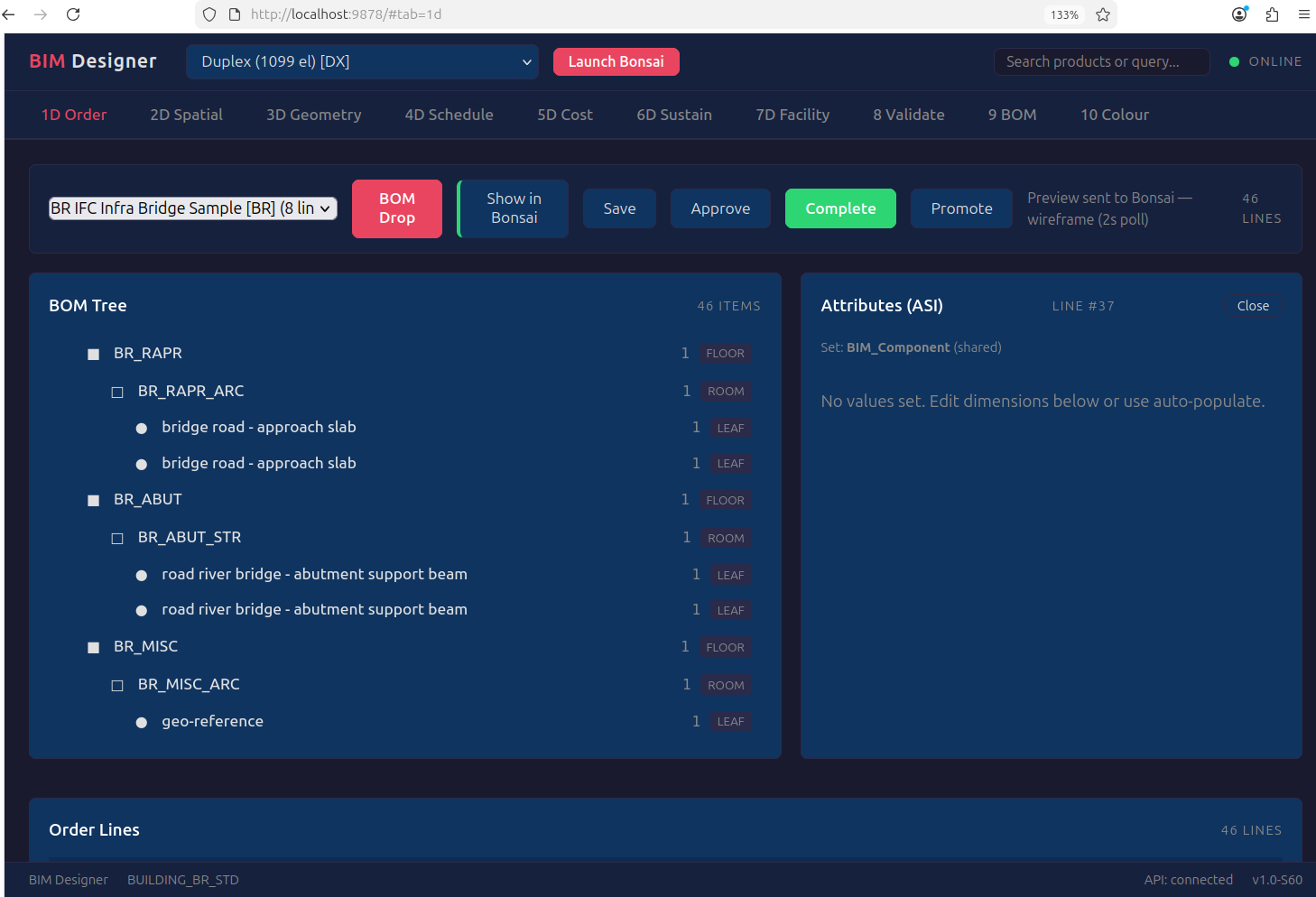
20.1 Why HTML, Not Blender Panels¶
Bonsai's built-in 4D scheduling (IFC5D sequence module) requires manual task
creation: the user draws a Gantt chart, links tasks to elements by hand, and
plays an animation. It is painting — the schedule exists because the user
typed it, not because the model implies it.
Our approach is the opposite. The BOM tree already encodes construction precedence — footings before columns, columns before beams, beams before slabs, MEP after structure. The 4D schedule is a topological sort of that tree. It generates itself. The same compiled output.db that powers 3D rendering also powers scheduling, costing, carbon, and facility management — as queries, not features.
This belongs in the HTML UI (port 9878), not in Blender panels, because:
- Multi-stakeholder — the project manager, QS, sustainability officer don't install Blender. They open a browser.
- C_Order lifecycle — DocAction (Draft → Approve → Complete) is an ERP workflow, not a 3D viewport operation.
- Cross-building — C_Project aggregates 200 buildings on one dashboard. Blender is single-scene.
- Real-time update — HTML reloads from output.db on each compile. No manual re-linking.
20.2 4D — Auto-Generated Construction Schedule¶
Source: output.db compiled elements +
CONSTRUCTION_SEQUENCE_RULES (IFC class → phase → predecessors)
| Feature | Implementation |
|---|---|
| Gantt chart | Auto-generated from BOM precedence. JS library (Frappe Gantt or equivalent) |
| Phases | Substructure → Superstructure → MEP Rough-in → Architecture → Finishes → Commissioning |
| Duration | Element quantity × labor productivity rates (CIDB Malaysia 2024) |
| Predecessors | Implicit from BOM tree: parent completes before children start |
| Per-storey | Each storey is a phase group — bottom-up construction sequence |
| Animation | Optional: push phase timestamps to Bonsai timeline via webui_sync |
How it differs from Bonsai 4D:
| Bonsai IFC5D | BIM Compiler HTML | |
|---|---|---|
| Task creation | Manual — user creates tasks | Auto — BOM tree implies sequence |
| Precedence | Manual — user links tasks | Auto — IFC class → phase → predecessors |
| Duration | Manual — user enters days | Calculated — qty × productivity rate |
| Cost link | None — separate workflow | Integrated — click phase → see 5D breakdown |
| Multi-building | Single file | C_Project — 200 buildings, one Gantt |
| Data source | IFC file (re-link on change) | output.db (regenerates on compile) |
20.3 5D — Cost Breakdown (Integrated with 4D)¶
Source: output.db elements × M_PriceList rates from component library
| Feature | Implementation |
|---|---|
| 3-component cost | Material + Labour + Equipment per element type |
| Rates | CIDB Malaysia 2024 productivity data (extensible per jurisdiction) |
| Grouping | By discipline, by storey, by phase, by element type |
| Phase cost | Each 4D phase shows its total cost — schedule and budget in one view |
| Variance | Base BOM cost vs exception order cost (thin order delta) |
| Export | Excel, CSV, JSON (iDempiere REST target: Phase H) |
The ERP insight: 5D is not a separate tool. It is SUM(price × qty) grouped
by whatever dimension the user wants — phase (4D), discipline (AD_Org), storey,
element type. One query, many views. This is what M_PriceList
does in iDempiere for manufacturing — price × BOM explosion = product cost.
20.4 6D — Sustainability (Carbon per Phase)¶
Source: output.db elements × carbon map from component library
Each element type has an embodied carbon coefficient (kgCO2e per unit). The 6D tab shows carbon by phase, by discipline, by storey — the same grouping as 5D but measuring environmental impact instead of cost. See TIER1_SRS.md.
20.5 7D — Facility Management (Asset Register)¶
Source: output.db elements × maintenance schedules from component library
COBie-compatible asset register: what's installed, where, when it needs maintenance, expected lifecycle. The 7D tab is the building's maintenance manual generated from the BOM. See TIER1_SRS.md.
20.6 8D — ERP Integration (iDempiere Write-Back)¶
The 8th dimension is the BIM Compiler itself — the BOM data model that makes all other dimensions queryable. The HTML UI manages the C_Order lifecycle and the target is iDempiere REST write-back (Phase H on roadmap): compiled C_Order + C_OrderLine pushed to a live iDempiere instance for procurement, invoicing, and project accounting.
20.7 HTML Tab Plan¶
| Tab | Dimension | Data Source | Status |
|---|---|---|---|
| BOM Tree | 1D | output.db spatial hierarchy | Live (port 9878) |
| Spatial View | 3D | output.db elements + Bonsai sync | Live |
| Schedule | 4D | output.db + precedence rules | Spec (this section) |
| Cost | 5D | output.db + M_PriceList | Spec (this section) |
| Carbon | 6D | output.db + carbon map | Python POC, Java migration pending |
| Facility | 7D | output.db + maintenance schedules | Python POC, Java migration pending |
| ERP | 8D | C_Order → iDempiere REST | Roadmap Phase H |
| Validation | HOW | AD_Val_Rule results | Live |
| Discipline | WHAT | AD_Org colour-coded breakdown | Live |
| DocAction | Process | DR → IP → CO → AP buttons | Live |
Industry sources: Snaptrude AI | Finch3D | BIMsmith Forge | TestFit | BIM Trends 2026 | Parametric BIM Libraries