2D Drawings → BIM (DXF2BIM) — User Guide
← Back to the User Guide · Modeller Guide · Home
Turn a set of 2D CAD drawings (.dxf) — floor plans, elevations, a roof plan and a section — into a 3D BIM
model inside the DAGeVu Modeller, and export it as IFC4 with real storeys.
It is deterministic: the same drawings and the same metadata give the same model, every time. No AI runs on your drawings — the code reads geometry and the labels you (or the drawing) state. Anything the drawing cannot tell it is listed as a gap, never guessed.
Status: preliminary (basic shapes). Walls, floor slabs, roof, door and window openings, and door/window fills. Proven end-to-end on the Duplex set and partly on an independent drawing. See What it does not do yet before you try your own drawings.
The idea in one picture
- A standard 2D set. Grid lines on the real wall axes (1, 2, 3… across; A, B, C… up, skipping I and O), dimension strings in three tiers (overall · grid-to-grid · detail), level marks, door swings, window sills.
- Metadata. Each sheet says what it is (plan of which level, which elevation face, roof, section) and the few facts geometry cannot decide (units, wall tops, door sizes from the schedule). The metadata lives inside the DXF, on its own layer, so the file stays a normal DXF any CAD program opens.
- A verdict. Before anything is built, the drawings are checked. Green = Qualifies. Red = a clickable list of exactly what is missing or inconsistent.
- Convert. One click builds the model. Every element remembers the DXF entity (handle and layer) it came from.
What a standard sheet looks like
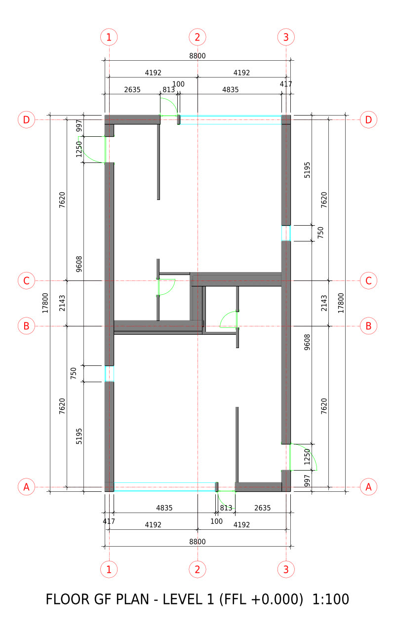
Ground floor plan of the Duplex, written from the model by the standard 2D writer. Grid bubbles at both ends; dimension strings: overall (8800 / 17800), grid-to-grid (4192 + 4192, 7620 / 2143 / 7620) and detail (walls and openings). Every dimension is a real CAD dimension measured between its two points — never typed text.
 |
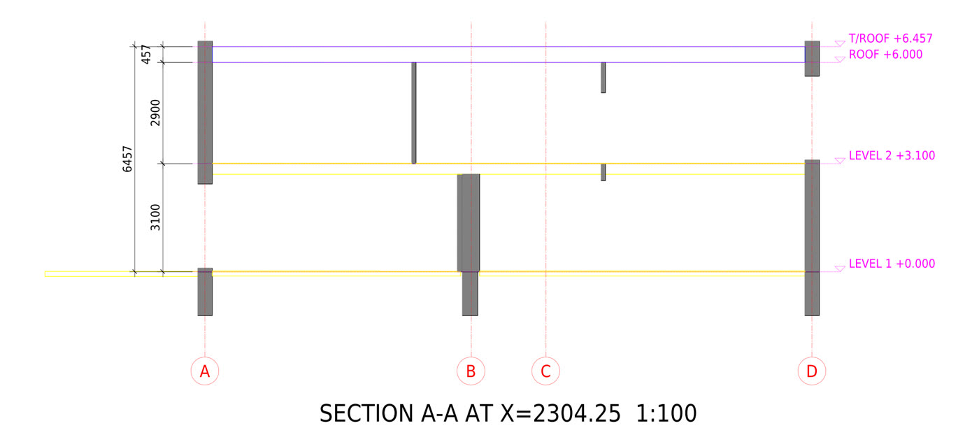 |
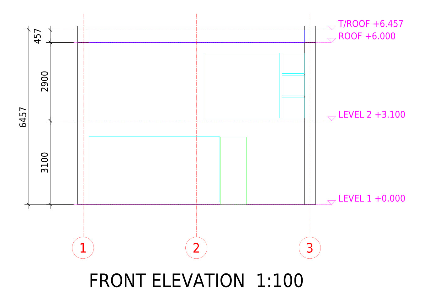
| Front elevation: walls and openings on that face, level datums and height dimensions. | Section: slabs and roof cut through, with their levels — this is where slab thickness comes from. |
Rules the writer follows (drafting conventions, stated as choices):
- A floor plan shows everything the cut plane passes through — cut at the storey level + 1.2 m.
- Grid lines sit on load-bearing and exterior wall axes, never snapped to a module.
- Door arcs: the hinge from the IFC door type (left/right hand), the swing side from the door leaf, the
radius = leaf width (not the frame). No hinge data → a
HINGE ?note, never a guessed arc. - Slab thickness is read from the section, not from elevations.
Step by step in the Modeller
Open: red1oon.github.io/bim-ootb/modeller/modeller.html (desktop browser).
1 · Open the drawings
📂 Open → Open 2D drawings (.dxf)… and select all sheets of the set at once (plans, elevations, roof, section). The 2D Drawings panel lists each sheet with its role; the canvas shows each sheet placed in 3D — plans at their level, elevations on their face, the section on its cut plane.

2 · Check the metadata
Press Metadata. The Drawing metadata panel shows, per section:
| Section | What you set | Notes |
|---|---|---|
| Sheets | role (plan / elevation / roof / section), level, face, cut | a plan's level defines a storey |
| Units | mm, m, in, ft | you confirm — the file header is shown ("file says mm") but never applied by itself |
| Layers | which layer holds walls, doors, glazing, dims, grid, levels; or ignore | templates for common layer standards |
| Tags | click an element on the canvas, pick its mark / type | e.g. a door mark that links to the schedule |
| Exclude areas | drag a box around decking, furniture, landscaping | its contents are ignored |
| Wall tops | "walls stop under the slab above", or a height per wall | interior wall heights are never visible in elevations |
| Verdict | live result | click an item to zoom to it on the drawing |
Every value shows where it came from: from file, from model, or you.

3 · Raw drawings: fill in what is missing
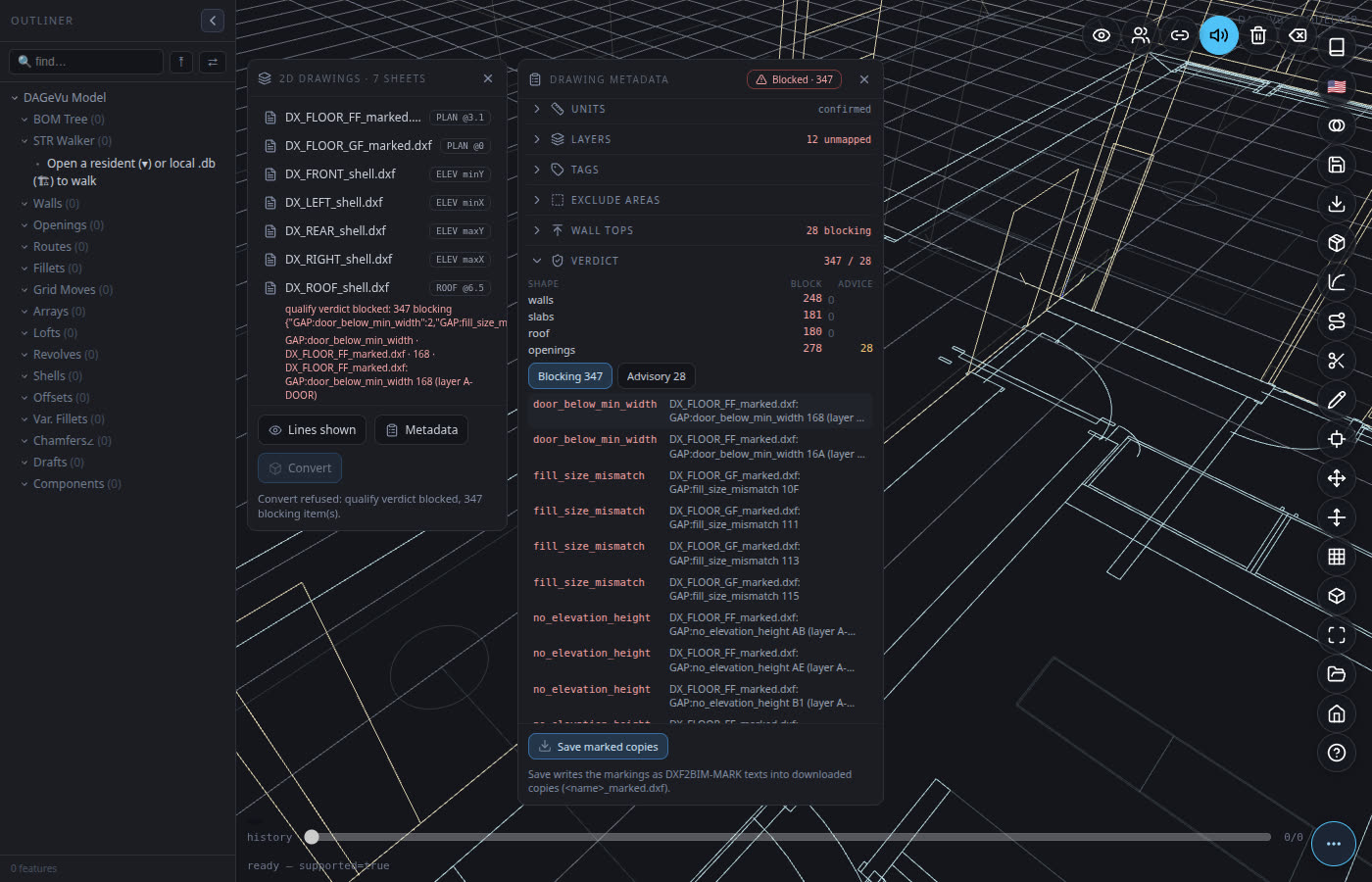
A drawing without metadata opens with red fields and the verdict Blocked. The editor lists suggestions it can prove from the drawing (e.g. a title text "GROUND FLOOR PLAN" → role = plan) — nothing becomes metadata until you tick it.
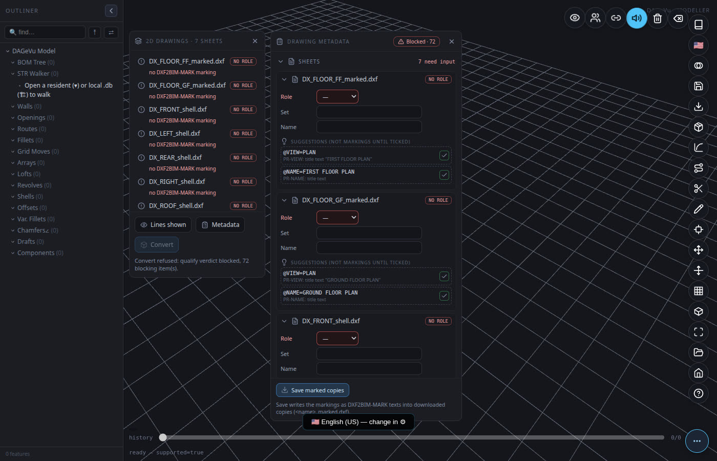
Click any verdict item to jump to it:
4 · Save the marked copies
Save marked copies downloads <name>_marked.dxf for every sheet, with your metadata written in. The
originals are never modified. Next time you open the marked copies, everything is already filled.
5 · Convert
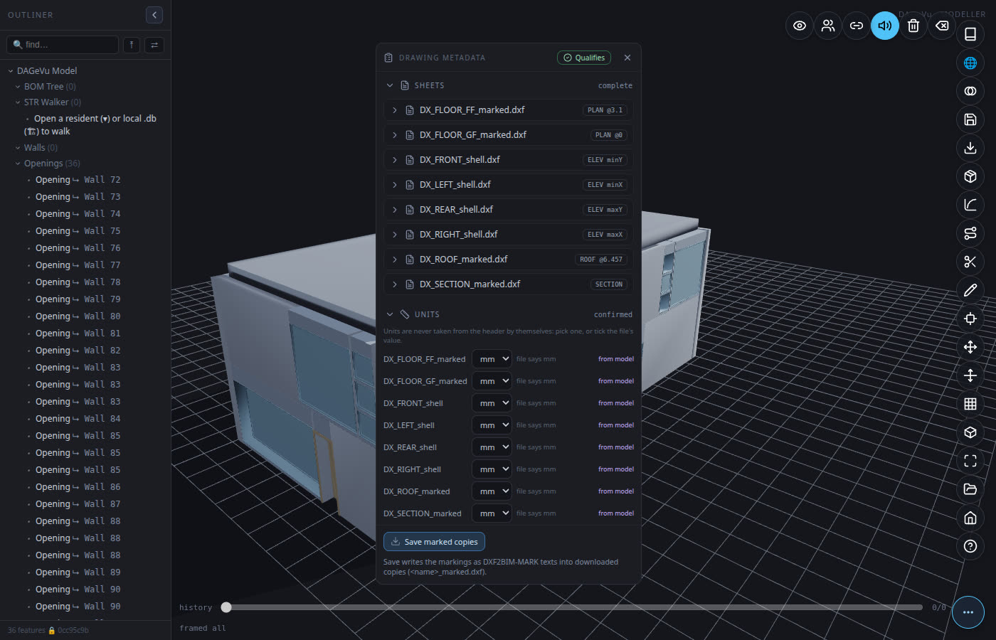
Convert is enabled only when the verdict is Qualifies. It builds walls, floor slabs, the roof, cuts the door and window openings, and places the door and window fills from the component library — as one undo step.
6 · Export IFC
Export → IFC4. The file has a proper spatial structure (Project → Site → Building → Storeys) and every element contained in its storey. On the Duplex standard set: 96 wall pieces, 2 slabs, 1 roof, 14 doors, 22 windows, 2 storeys.
The metadata, for CAD users
Metadata is plain text on the layer DXF2BIM-MARK, one marking per text entity, @KEY=value. You can type
it in any CAD program, or let the editor write it.
| Marking | Example | Meaning |
|---|---|---|
@VIEW |
@VIEW=PLAN · ELEV · ROOF · SECTION |
what the sheet is |
@LEVEL |
@LEVEL=3.1 |
plan level (m) — defines the storey |
@FACE |
@FACE=minY |
which building face an elevation shows |
@CUT |
@CUT=X,2304.25 |
where a section cuts (drawing units) |
@ROOF |
@ROOF=6.457 |
roof top level |
@UNITS |
@UNITS=mm |
drawing units |
@REGION / @EXCLUDE |
rectangles | the part of the sheet that is the view / areas to ignore |
@LAYER |
@LAYER=A-WALL,wall |
what a layer means on this sheet |
@TAG |
@TAG=door,D3 |
the mark of the element under the text |
@SCHEDULE |
@SCHEDULE=D3,door,900,2100 |
a schedule row (size of a mark) |
@WALLTOP |
@WALLTOP=3.1,slab_above · @WALLTOP=handle:99,5.695 |
interior wall heights |
@BY (suffix) |
@LEVEL=3.1 @BY=user |
who stated it: user or model; no suffix = stated in the file |
One rule governs it all: geometry is what is drawn and dimensioned; a label states only what geometry
cannot decide (which product, which schedule mark, how tall an interior wall is). A difference between the
drawing and its schedule is reported (GAP:schedule_conflict), never silently resolved.
What it does not do yet
Honest limits of the preliminary version:
- Basic shapes only: walls, slabs, roof, openings, door/window fills. No stairs, ramps, MEP, furniture.
- Rectilinear buildings: skewed and curved walls are reported as gaps; roofs are flat outlines (pitched or curved roofs are not drawn correctly yet).
- Columns are cut and drawn, but not yet as column symbols on the grid.
- Openings above or below the plan cut (e.g. high bathroom windows) — being changed so every opening of the storey is shown from its host wall regardless of height.
- "Any DXF" is not claimed. Your drawing needs the metadata above; the editor helps you add it, the verdict tells you when it is complete.
- The component library (door/window geometry) is loaded locally during this preliminary stage; on the public site Convert reports the library as unreachable until it is published.
For developers
The same pipeline runs in Node (BIMCompiler repo):
# standard 2D set from a model DB (+ door operations extracted from the IFC by scripts/extractIFC2DB.js)
python3 2D_Layout/python/std2d.py <model_extracted.db> --out 2D_Layout/output/STD --door-ops <door_ops.db>
node tests/dxf2bim/mark_dx_set.js std <door_ops.db>        # metadata from the model (@BY=model)
DXSET=std node tests/dxf2bim/rosetta_dx_shell.js           # basic shapes, checked against the model
node tests/dxf2bim/rosetta_qualify.js                      # the verdict for every test set
Specs: DXF2BIM spec · Basic shapes spec ·
Reader user guide. Modeller lane spec: prompts/DXF2BIM_MODELLER_LANE.md (bim-ootb).
Every check has a deliberately broken control that must fail. Code is MIT licensed.
Test drawing credit: the American Farmhouse drawings used as an independent test are by Jay Osborne (freefarmhouse.com), CC BY-SA; they are not included in the repository.